Switching input modes, Making tuning panel settings – Yaskawa MP900 Series Machine Controller for Standard Operation User Manual
Page 462
7.6 Tools
7-95
7
Switching Input Modes
There are two input modes for tuning panels: Table Definition Input Mode where entries are
made for all cells in the table; and Register Input Mode where only register numbers are
input. The cursor position can be set to vertical, horizontal or no movement after the inputs
have been made and the Enter Key pressed.
The method for switching input modes is the same as for table programs. Refer to 7.4.4
Switching Input Modes.
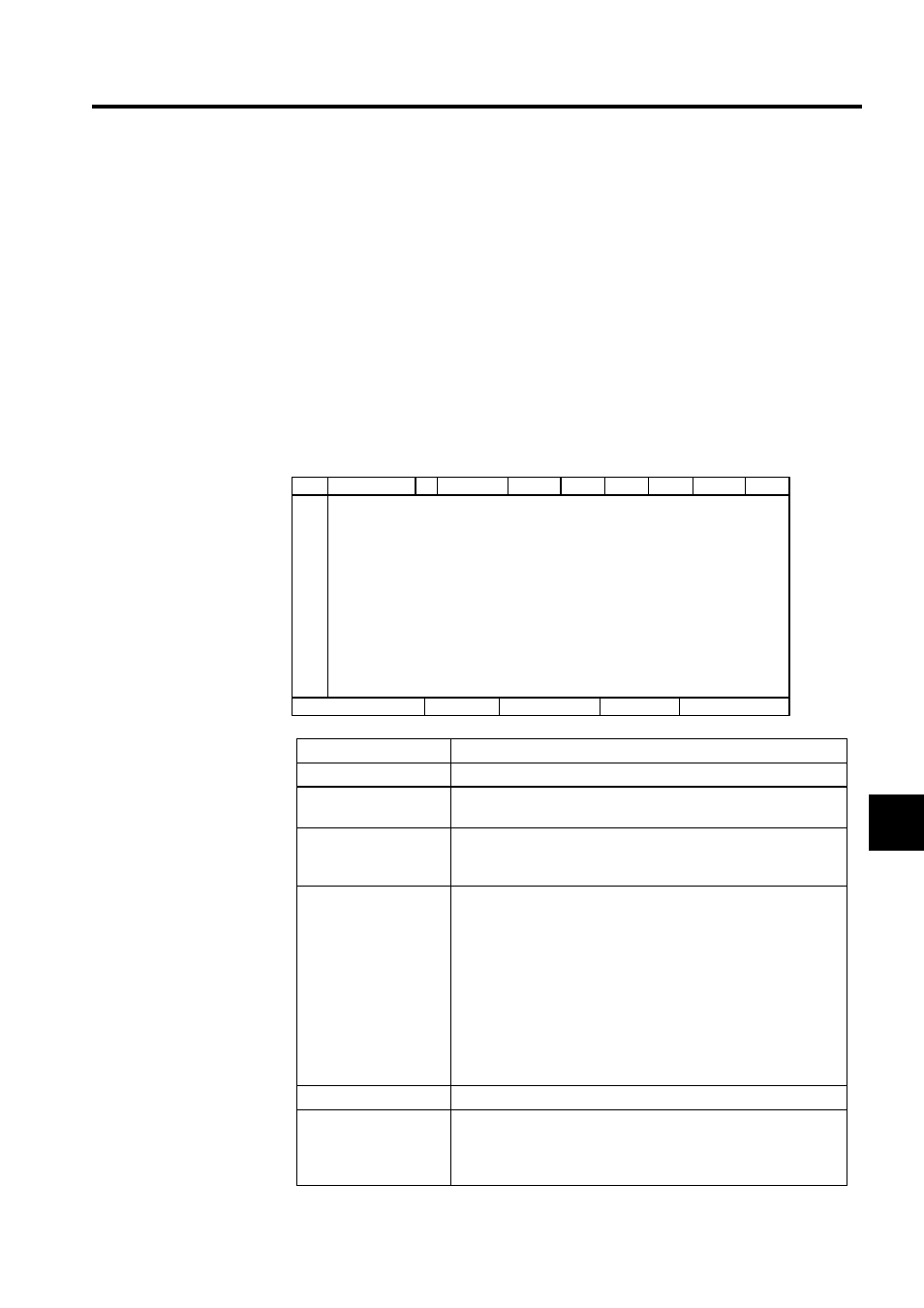
Making Tuning Panel Settings
All definition data for tuning panels can be entered. Up to 100 definition data items can be
created.
Setting
Explanation
Data Name
Enter a data name of up to 48 characters.
S
Enter S to permit current values to be set. If this cell is left blank, it
will not be possible to change the current value.
Disp. Def. (Display
Definition)
Enter the display format for current values: "X" for numerals and "."
for decimal points. Input examples for table definitions are shown in
the Table Formats table following this table.
Current Value
Current values for the registers will be displayed. Register data from
the Machine Controller is displayed in Online Mode, and data from
the hard disk will be displayed in Offline Mode. If "x.xxx" is input in
the Disp. Def. column, the display will be "1.000" even if the actual
register value is 1000.
The current value can be changed if "S" is input in the Setting Per-
missions column. The input value is saved when the Enter Key is
pressed.
If respective values are specified in the Lower Limit and Upper Limit
columns, only values in that range can be entered as the current
value.
Unit
Enter the unit for the current value of up to 8 characters.
Lower Limit
Enter the lower limit for the current value. If the same value is set for
both the upper and lower limits, that value is the only current value
that can be entered. Enter upper and lower limits such that the lower
value is equal to or less than the upper limit.
No.
S
REG-No. DWG
Data Name
Disp. Def.
Current
Value
Unit
Lower
Limit
Upper
Limit
DWG No.
Input Mode