4 setting module configuration definitions, Configuration information, Rack and slot information – Yaskawa MP900 Series Machine Controller for Standard Operation User Manual
Page 230
3.7 MP940 Module Definitions
3-135
3
3.7.4 Setting Module Configuration Definitions
Configuration Information
This window consists of tab pages used to define the slots of each rack, and the rack settings.
A maximum 4-rack Machine Controller can be set with the CP-717, but the number of racks
is limited to 1 rack for the MP940. Racks 1 to 3 cannot be set.
The maximum number of function Modules (i.e., the number of slots) that can be mounted
to each rack is nine, but the MP940 is an all-in-one type, so its settings are limited to a max-
imum of six slots. The Modules allocated to these slots cannot be changed.
Rack 1:
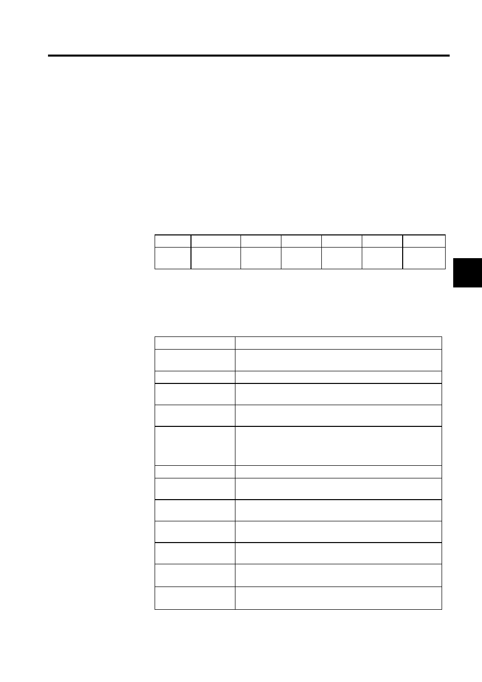
Rack and Slot Information
An MP940 virtual rack is allocated to the tab page for rack 1. Slot numbers are displayed in
the columns from left to right and setting items are displayed in rows from top to bottom.
Slot 00
Slot 01
Slot 02
Slot 03
Slot 04
Slot 05
Slot 06
MP940
RESERVED
SERIAL
LIO
SVA
CNTR
MLINK or
260IF
Setting Item
Details
Select Rank,
Rack Kind
Set information on the rack. The MP930 is set automatically to rack
1 and short rack.
No.
This row shows the virtual slot numbers of the slots in the rack.
Module
The Module is set automatically using the Module name set in each
slot.
Control CPU No
Set the number of the CPU to control each Module. The MP940
CPU is set automatically to 01.
Cir No.
Circuit numbers are set for each type of Module starting from 01 for
Communications and Motion Modules. With the MP940, this would
be the Serial, SVA, and MLINK Modules. There is only one of each
kind of Module, so the Cir No is set automatically to 01 for each.
Module (Dual)
The Dual Modules Setting is not supported in the current version.
Cir (Dual)
Dual Transmission Paths Setting is not supported in the current ver-
sion.
Replacement
Hot Swapping (Removal/insertion under power) is not supported in
the current version.
I/O Start Register
Set the address of the leading I/O register. Refer to the settings for
LIO, CNTR, and MLINK.
I/O End Register
Set the address of the ending I/O register. Refer to the settings for
LIO, CNTR, and MLINK.
Input DISABLE
Controls each Module's Input Enable/Disable setting.
Blank: Setting not possible, D: Disabled, E: Enabled
Output DISABLE
Controls each Module's Output Enable/Disable setting.
Blank: Setting not possible, D: Disabled, E: Enabled