Control cpu no, Info – Yaskawa MP900 Series Machine Controller for Standard Operation User Manual
Page 118
3.5 MP920 Module Definitions
3-23
3
When a Module requiring two slots (MP920 or SVA-01) is selected, "RESERVED" will be
displayed in the next slot number's Module row and another Module can't be defined in that
slot. If another Module has already been defined in the next slot, either delete that Module or
define it in a different slot.
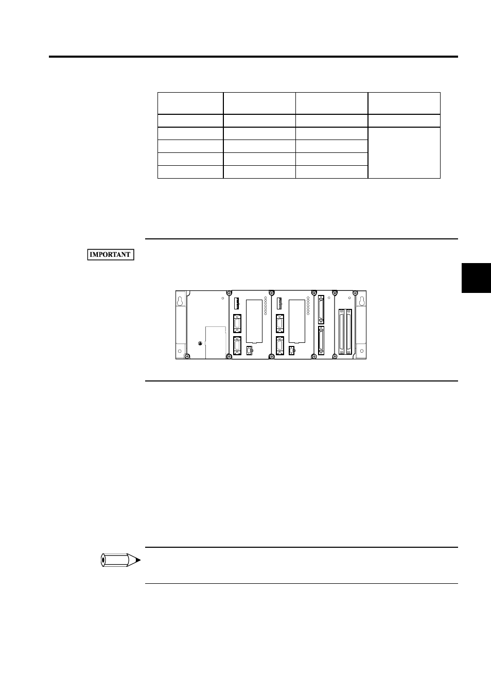
The MP920, CPU Modules must be mounted in slots 00 and 02 of rack 1. When a single CPU Module
is used, mount it in slot 00; when two CPU Modules are used, mount them in slot 00 and slot 02.
The following diagram shows a multiple-CPU configuration.
Control CPU No.
Input the CPU number of the CPU which controls each Module.
Input "1" to select the CPU Module in slot 0 or "2" to select the CPU Module in slot 2. Input
"1" for a single-CPU configuration. An error will occur when the settings are saved if the
Control CPU Number is set to "2" but there is only one CPU Module.
Input "1" for the SVA, PO-01, and SVB Modules regardless of the CPU configuration.
It is not necessary to input a Control CPU Number for the MP920 CPU Module or an
EXIOIF Module.
An error will occur when the settings are saved if different Control CPU Numbers are set for
Dual Modules.
To use the multiple-CPU configuration, multiple CPUs must be specified when creating a new PLC
folder with the File Manager. See 2.1 File Manager for details.
1. CPU Configuration
a) Single/Multiple CPU
There are two CPU configurations: The single CPU configuration and the multiple
CNTR-01
CNTR-01 Module
1
SVA-01
SVA Module
2
Enabled with Control
CPU number 1.
PO-01
PO-01 Module
1
SVB-01
SVB-01 Module
1
SVA-02
SVA-02 Module
1
Item
Module
No. of Occupied
Slots
Remarks
Slot No.
00
01
02
03
04
SW1
L.RST
RUN
INIT
TEST
MULTI
FLASH
M.RST
ON
OFF
ON
1
2
3
456
78
PORT2
PORT1
CN1
RLY OUT
BATTERY
RDY
PRT1
RUN
ALM
ERR
BAT
ALM
PRT2
MP920 CPU-01
SW1
L.RST
RUN
INIT
TEST
MULTI
FLASH
M.RST
ON
OFF
ON
1
2
3
456
78
PORT2
PORT1
CN1
RLY OUT
BATTERY
RDY
PRT1
RUN
ALM
ERR
BAT
ALM
PRT2
MP920 CPU-01
DI-01
CN1
CN2
RUN
EXIOF
CN1
IN
RUN
CN2
OUT
PS-03
DC24V
POWER
TB1
+24V
0V
FG
SG
INFO