18 po-01 motion parameters settings, Outline of po-01 motion parameter settings – Yaskawa MP900 Series Machine Controller for Standard Operation User Manual
Page 188
3.5 MP920 Module Definitions
3-93
3
Refer to MP920 Machine Controller User's Manual: Design and Maintenance (SIEZ-C887-2.1) or
MP920 Machine Controller User's Manual: Motion Module (SIEZ-C887-2.5) for details on monitor
parameter settings.
Saving, Deleting, and Closing the SVA Motion Parameters
Refer to the procedures in 3.3 Basic Individual Module Definition Operations for details.
1 This operation deletes the SVA motion fixed parameters and setting parameters of all axes.
2 The edited motion fixed parameters cannot be saved if the RUN (Servo ON) Flag is ON. Save the
motion parameters data after this flag has gone OFF.
The RUN (Servo ON) Flag is bit 0 of parameter number 2 (RUN Command Settings) in the Set Up
Parameters Tab. The register number for parameter 2 is OWC001.
3 The Save (S) command saves the motion fixed parameters for all axes of the servo number currently
being displayed.
4 The Error Detection Message Box is displayed if the data was not saved successfully. Refer to Appen-
dix A Error Messages, eliminate the cause of the error, and save the data again.
3.5.18 PO-01 Motion Parameters Settings
This section explains how to set the motion parameters of the PO-01 Module.
Outline of PO-01 Motion Parameter Settings
The PO-01 Module is a pulse-train output Motion Control Module. One PO-01 Module can
be connected to up to 4 pulse motor drivers (4 axes).
Two connectors (CN1 and CN2) are provided for connections to pulse motor drivers. Each
connector is equipped with 2 (5-V differential) pulse-train outputs, 4 digital outputs (DO)
and 5 digital inputs (DI) for various pulse driver control applications.
To set the motion parameters, the required data must be set (or referenced) in three tab
pages: the Fixed Parameters Tab, Set Up Parameters Tab, and Monitor Tab.
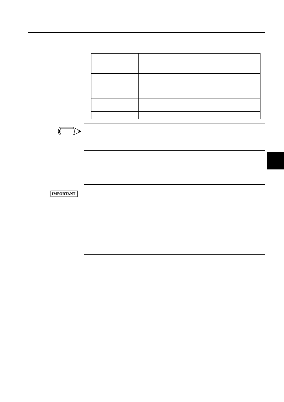
Setting Item
Details
Axis Number
Select the desired axis number (axis 1 to axis 4). The parameters for
each axis are displayed.
Parameter Name
Displays the parameter name.
REG-No.
Displays the number of the register that corresponds to the parameter
name. The range of registers depends on the servo number currently
being displayed. See Table 3.15 Register Ranges for details.
Monitor Data
In online mode, the current values of the parameters are displayed.
In offline mode, nothing will be displayed.
Unit
Displays the units of the parameter.
INFO