Yaskawa MP900 Series Machine Controller for Standard Operation User Manual
Page 395
Ladder Logic Programming
7.3.5 Entering Ladder Instructions
7-28
7
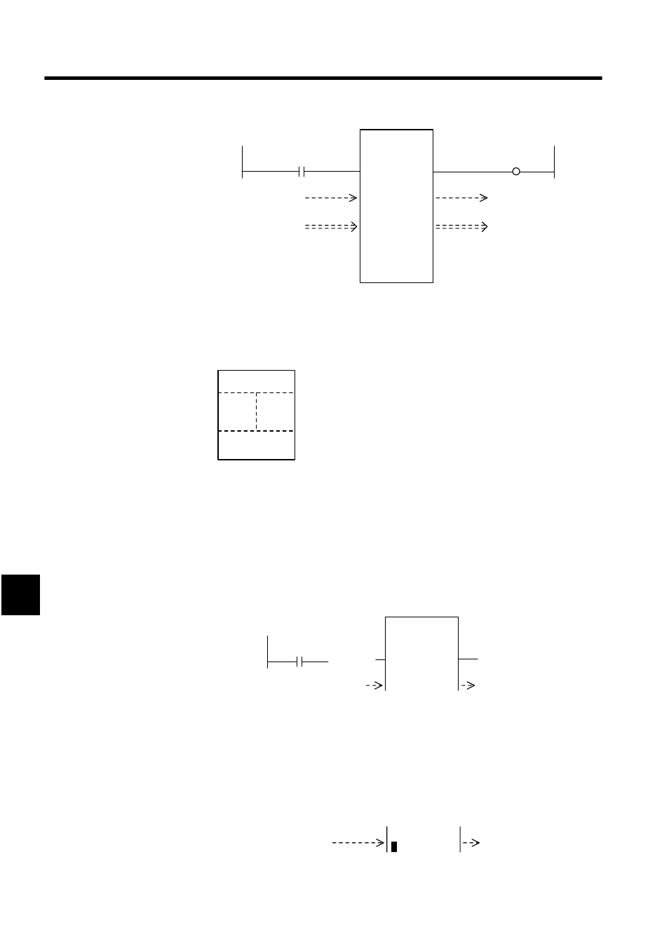
1. Creating the Function Box
• Select the FSTART instruction and enter the function name, FUNC-01.
The function box will be displayed.
Next, create the function input section, address input section, and output section as
described below.
2. Entering the Inputs
The following example is for inputting bits (defined using B-VAL).
a) Enter the N.O. CONTACT instruction and the bit register number MB000001.
b) Input the FIN instruction. The function input parameters and the N.O. CONTACT
instruction will be connected.
Create the input section for integer data (defined using I-VAL), double-length integer
data (defined using L-VAL), or real number data (defined using F-VAL) as follows:
The following example is for integer data.
c) Enter the INTEGER ENTRY instruction and the register address, MW00010.
d) Input the FIN instruction. The function input parameters and the INTEGER ENTRY
instruction will be connected.
1 0001
MB000001
1 0003
[├ MW00010 ]
⇒
MW00011
FUNC-01
IN-1
OUT-1
FIN
FOUT
IN-2
OUT-2
FIN
FOUT
IN-3
OUT-3
FIN
FOUT
ADDRESS
MA01000
1 0000
MW00021
1 0005
MW00020
1 0006
MB000002
Function Box
Function name
Inputs
Outputs
Addresses
1 0001
MB000001
FUNC-01
IN-1
OUT-1
IN-2
OUT-2
1 0000
F
FIN
1 0003
├
MW00010
IN-2
OUT-2
FIN
F