8 inputting interlock table data, 8 inputting interlock table, Data – Yaskawa MP900 Series Machine Controller for Standard Operation User Manual
Page 425: Inputting table data
Ladder Logic Programming
7.4.8 Inputting Interlock Table Data
7-58
7
7.4.8 Inputting Interlock Table
1
Data
Interlock tables define the device startup and operation and other interlock conditions. Inter-
lock conditions are defined by inputting symbols, bit register numbers, and signal type (N.O.
CONTACT, N.C. CONTACT, or COIL). When an interlock table is saved, it is automati-
cally converted to a subroutine made up of N.O. CONTACTs, N.C. CONTACTs, and
COILs. Subroutines can be called by using the XCALL instruction in the main program.
Refer to the following sections.
• Inputting table data
• Switching between subtables and main tables
• Splitting and joining blocks
• Registering comments
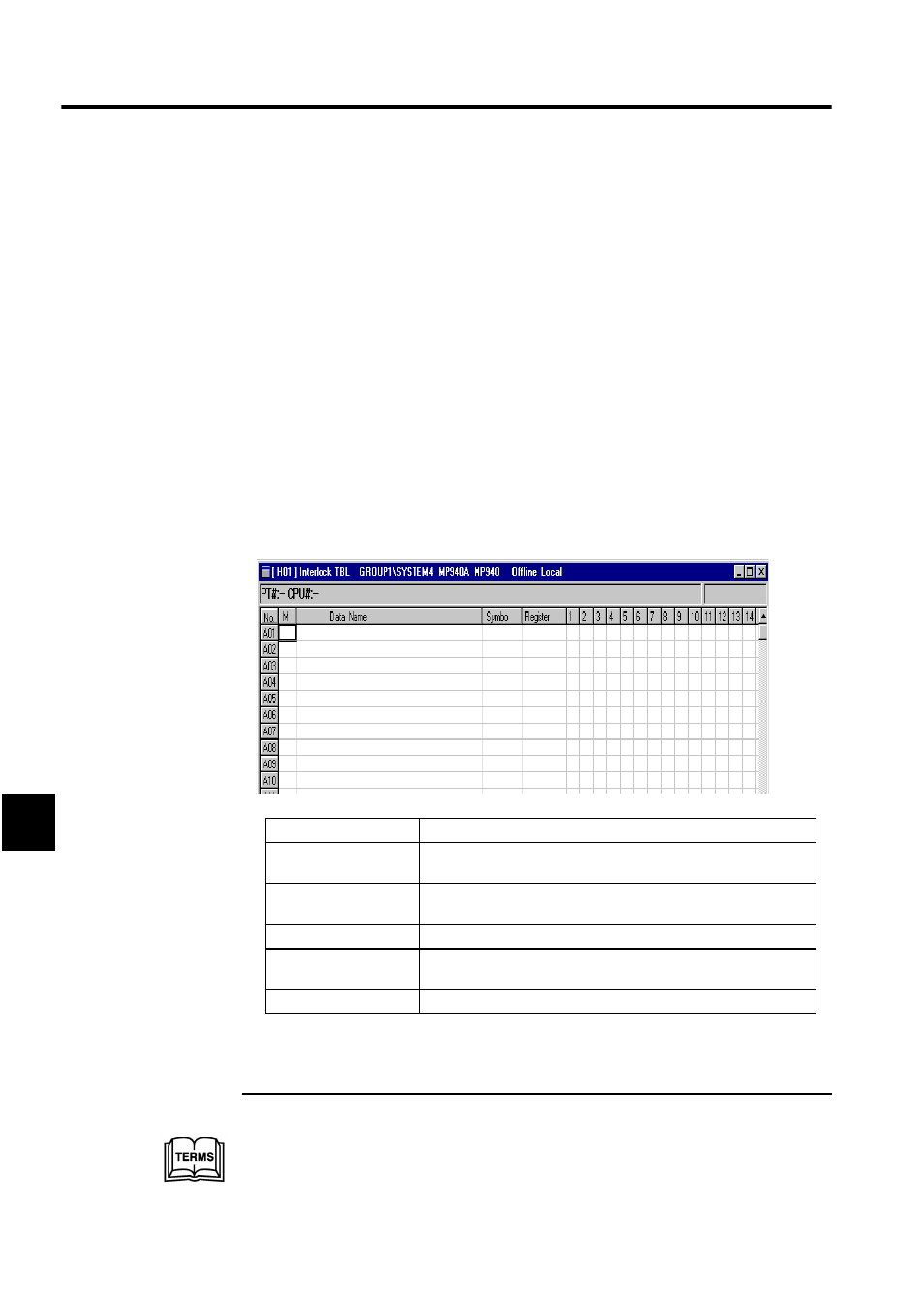
Inputting Table Data
Up to 500 rows and 25 columns of table data can be entered.
1
Interlock tables
Interlock tables are a type of table program that show device startup and operating condi-
tions.
Setting Item
Details
No.
The row number for each block is displayed. The blocks are num-
bered alphabetically, and are followed by a numeric row number.
M
Enter the input mode for interlock conditions as one letter: I, S, O, or
X. Refer to the Interlock I/O Modes table given after this table.
Data Name
Enter a name of up to 48 characters.
Symbol
Enter a symbol of up to 8 characters to be used for the register num-
ber to be interlocked.
Register
Enter the bit register number that controls the interlock.