9 cntr i/o definitions – Yaskawa MP900 Series Machine Controller for Standard Operation User Manual
Page 242
3.7 MP940 Module Definitions
3-147
3
Refer to 6.3.3 Motion Monitoring Parameter Details in the MP940 Machine Controller
User's Manual: Design and Maintenance (SIEZ-C887-4.1) for details.
Saving, Deleting, and Closing MP930 Motion Parameter Definitions
Refer to the procedures in 3.3 Basic Individual Module Definition Operations for details.
1 The edited motion fixed parameters cannot be saved if the RUN (Servo ON) Flag is ON. Save the
motion parameters data after this flag has gone OFF.
The RUN (Servo ON) Flag is bit 0 of parameter number 2 (RUN Command Settings) in the Set Up
Parameters Tab. The register number for parameter 2 is OWC001.
2 The Save (S) command saves the motion fixed parameters for all axes of the servo number currently
being displayed.
3 The Error Detection Message Box is displayed if the data was not saved successfully. Refer to Appen-
dix A Error Messages, eliminate the cause of the error, and save the data again.
3.7.9 CNTR I/O Definitions
The MP940 CNTR Module provides 1 pulse input (PI) with a 5-V differential interface.
The CNTR Module has a Latch Input Signal, so the counter value can be latched when the
latch signal is received. A Coincident Detection Signal Output is also provided, so a signal
can be output to an external device when the count matches an internal set value.
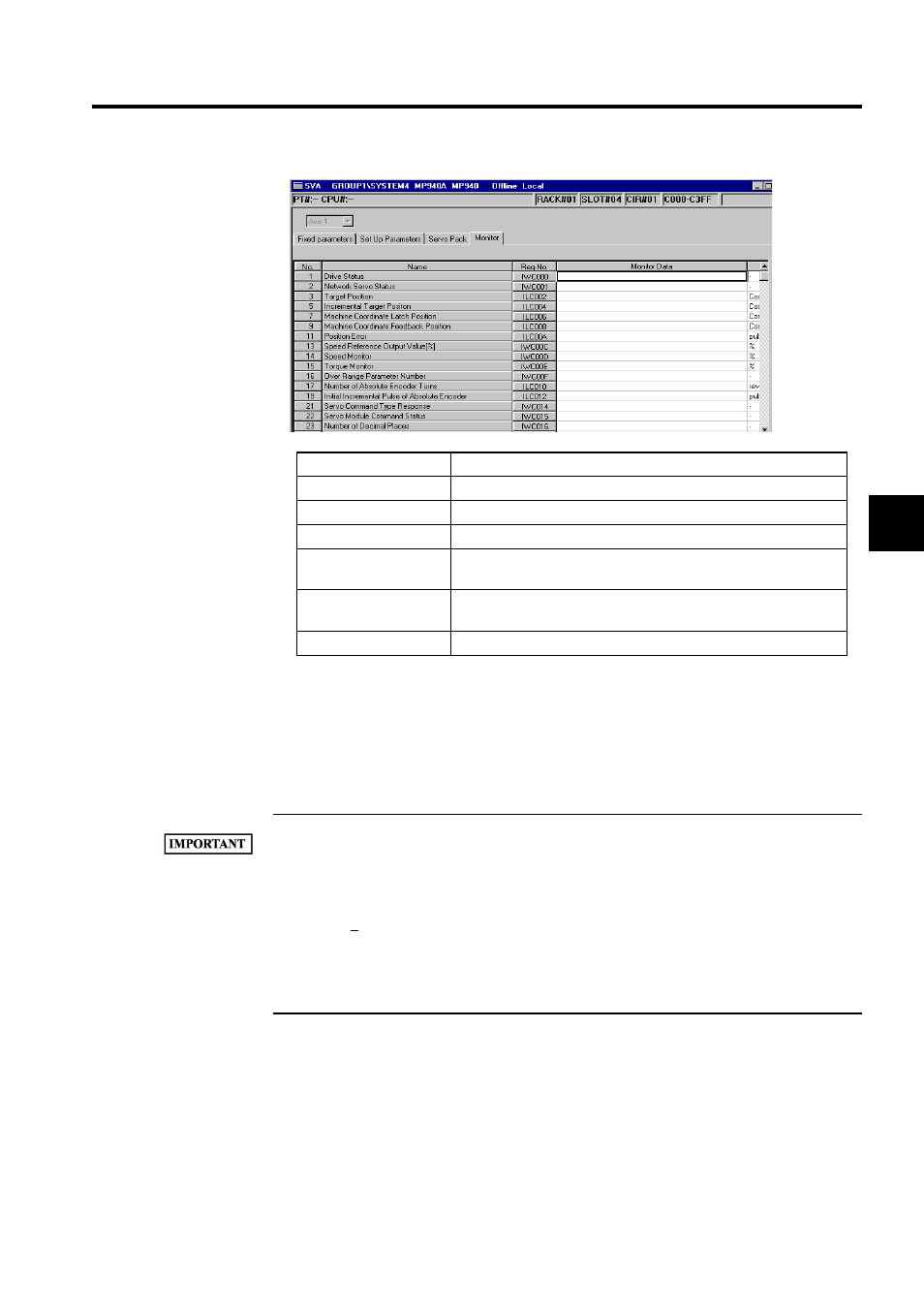
Setting Item
Details
Axis Number
Displays the axis number. The axis is fixed at Axis 1.
No.
Displays the number of the monitor parameter.
Parameter Name
Displays the parameter name.
Reg-No.
Displays the register number corresponding to the monitor parame-
ter.
Monitor Data
In online mode, the parameter's current value will be displayed. In
offline mode, nothing will be displayed.
Unit
Displays the unit for setting the data.