Tab pages, Serial communications definitions, Cp-217 transmission definitions – Yaskawa MP900 Series Machine Controller for Standard Operation User Manual
Page 233

Module Configuration Definitions
3.7.6 Serial Transmission Definitions
3-138
3
Tab Pages
Use the tab pages to set the parameters for the Serial Module. There are two tab pages, one
for each port.
When the Serial Definitions Window is opened without any settings having been made previously, a
Create New Message Box will be displayed. Click the OK Button to proceed to the next operation.
Serial Communications Definitions
Two CIR# definition tabs are displayed in the Serial Definitions Window. Make the defini-
tions while switching between the tabs as required.
CP-217 Transmission Definitions
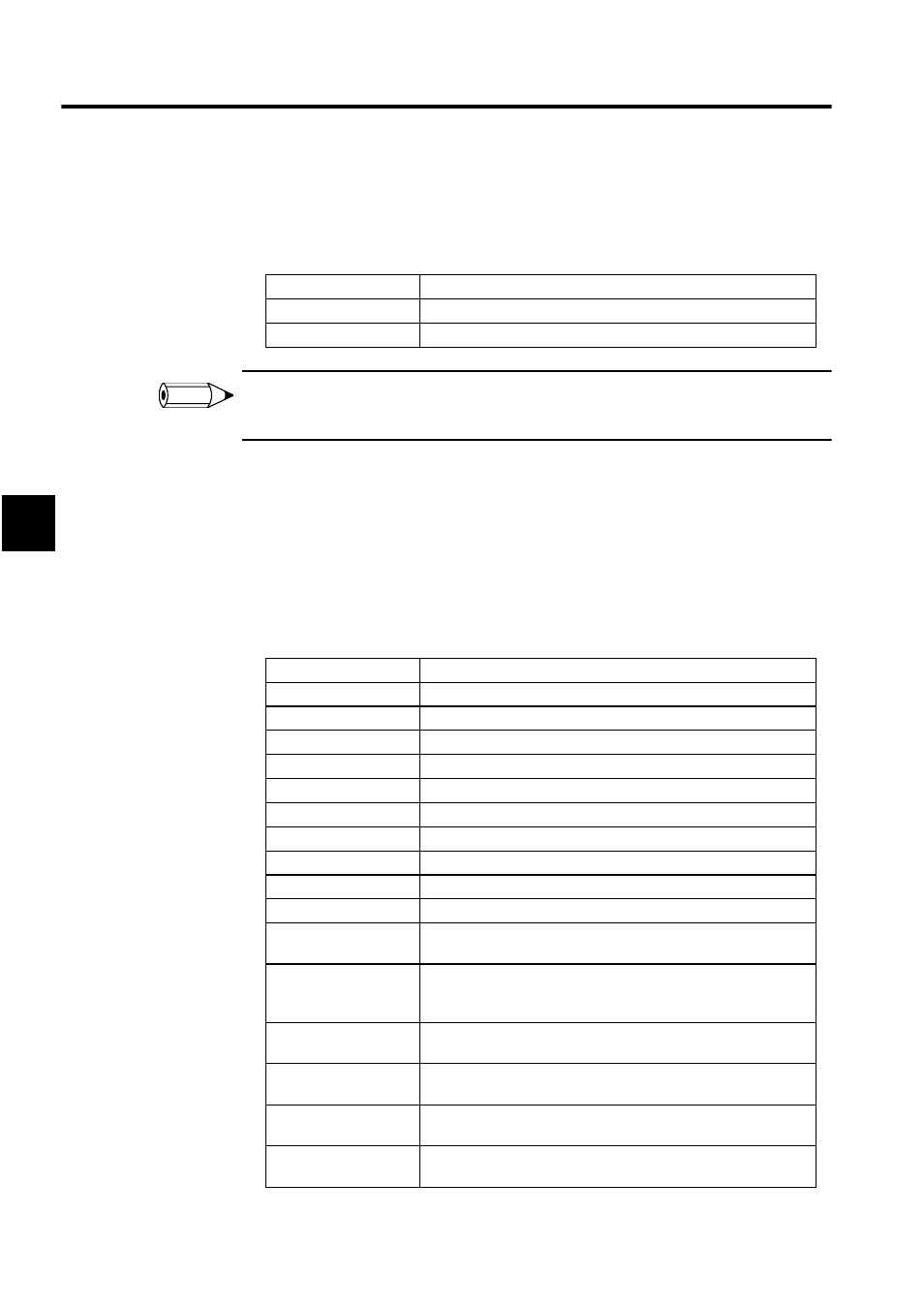
The definitions for CP-217 transmission are listed in the following table.
Tab Page
Details
CIR#01
Sets the RS-232C transmission parameters.
CIR#02
Sets the RS-422/485 transmission parameters.
Setting Item
Details
Circuit Number
Select the CIR# for the tab page.
Transmission Protocol
Select from MEMOBUS, MELSEC, or no protocol.
Master/Slave
Select whether the Module is a master or a slave.
Device Address
Set the master’s address to 0, and slave addresses from 1 to 63.
Serial I/F
Select RS-232 (RS-232C), RS-485, or RS-422.
Transmission Mode
Select from RTU, ASCII, or none.
Data Length
8Bit: 8 bits; 7Bit: 7 bits
Parity Bit
Select even, odd, or none (no parity).
Stop Bit
1stop: 1 stop bit; 2stop: 2 stop bits
Baud Rate
Select the transmission speed (bps).
Sending (Send Delay)
Set the delay between executing the send/receive functions (MSG-
SND OR MSG-RCV) and sending the message.
Automatically
Reception
(Automatic Reception)
Set whether or not to automatically respond to quires from the mas-
ter.
Readout of Input Relay Set the leading address and range of the input relays that can be read
for automatic response.
Readout of Input
Registers
Set the leading address and range of the input registers that can be
read for automatic response.
Readout/Write-in of
Coil
Set the leading address and range of the coils that can be read/written
for automatic response.
Readout/Write-in of
Hold Register
Set the leading address and range of the holding registers that can be
read/written for automatic response.
INFO
