Inputting table data, Normal display, Switching part units – Yaskawa MP900 Series Machine Controller for Standard Operation User Manual
Page 428
7.4 Creating Table Programs
7-61
7
• Inputting table data
• Switching part units
• Switching table formats
Inputting Table Data
Up to 100 rows of table data can be entered. Only 32 columns in total of input and output
data, however, can be entered.
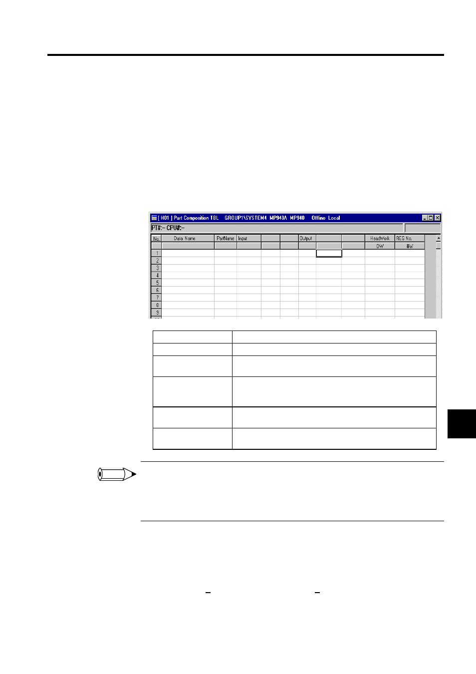
Normal Display
1 Component assembly tables cannot be created for user functions.
2 The default number of columns for the input and output sections of the part composition table will con-
tain three columns each by default. The number of columns must be increased beforehand when input-
ting functions with four or more I/Os in the Part Name column.
Switching Part Units
The procedure to switch between single part or multiple part composition tables is shown
below.
1. Select View (V) and then Designate Part Unit (P) from the table program menus. The
Part Unit Selection Window will be displayed.
Setting Item
Details
Data Name
Enter a name of up to 36 characters.
Part Name
Enter an existing user function signal. After the signal is input the I/
O signals for user functions will be displayed automatically.
Input
Enter the input register numbers or direct values to be allocated to
each user function input. Put an "Ho" in front of numeric values
when inputting in hexadecimal.
Output
Enter the output register numbers for allocating each user function
output.
Head Work
Enter the D register number or # register number for allocating the
work registers used within the user function.
INFO