Motion start register, Motion end register, Detail – Yaskawa MP900 Series Machine Controller for Standard Operation User Manual
Page 124
3.5 MP920 Module Definitions
3-29
3
• Blank:Disable specification not allowed.
• D: Outputs disabled.
• E: Outputs enabled.
Select "D" to disable or "E" to enable.
Modules marked with a "-" in the I/O disabled column cannot be disabled.
An error will occur when the settings are saved if Dual Modules has been set but the Mod-
ules have different I/O DISABLE settings.
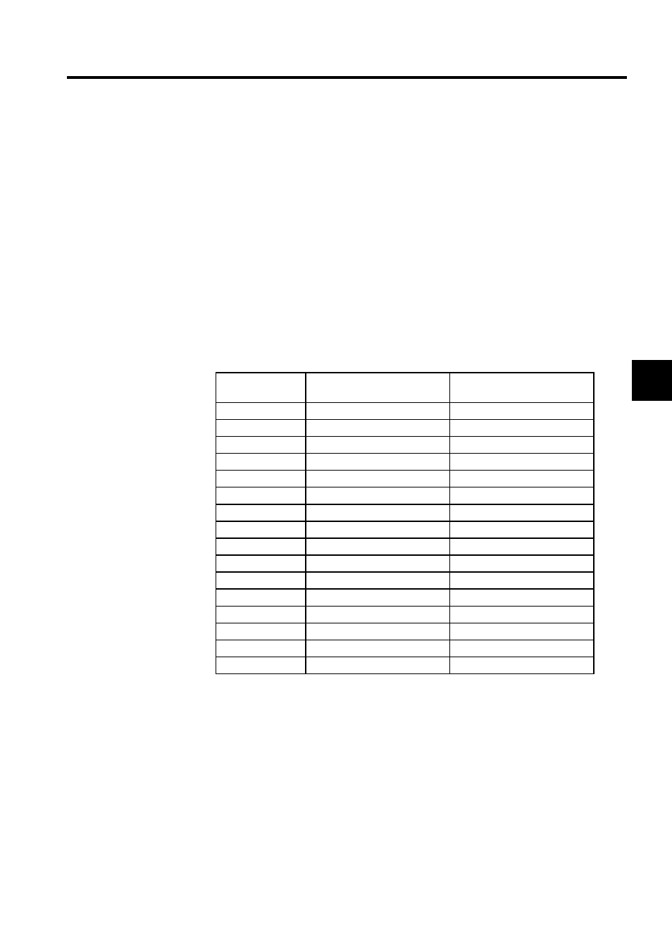
Motion Start Register
With Motion Modules (SVA-01, SVA-02, PO-01, and SVB-01), this row displays the motion
parameter register's leading offset address, which is allocated according to the circuit num-
ber (Motion Module number) setting for the Module. The Motion Start Register cannot be
set.
Motion End Register
With Motion Modules (SVA-01, SVA-02, PO-01, and SVB-01), this row displays the motion
parameter register's ending offset address, which is allocated according to the circuit number
(Motion Module number) setting for the Module. The Motion End Register cannot be set.
Detail
This heading was provided to indicate a second set of individual definitions when the Mod-
ule assigned to the slot has individual definitions that are divided into more than one group.
For example, both MECHATROLINK Interface Definitions and Servo Parameter Defini-
Motion Module
Number
Leading Register Number
(Motion Start Register)
Ending Register Number
(Motion End Register)
1
C000
C3FF
2
C400
C7FF
3
C800
CBFF
4
CC00
CFFF
5
D000
D3FF
6
D400
D7FF
7
D800
DBFF
8
DC00
DFFF
9
E000
E3FF
10
E400
E7FF
11
E800
EBFF
12
EC00
EFFF
13
F000
E3FF
14
F400
E7FF
15
F800
EBFF
16
FC00
EFFF