Yaskawa MP900 Series Machine Controller for Standard Operation User Manual
Page 119
Module Configuration Definitions
3.5.3 Setting Module Configuration Definitions
3-24
3
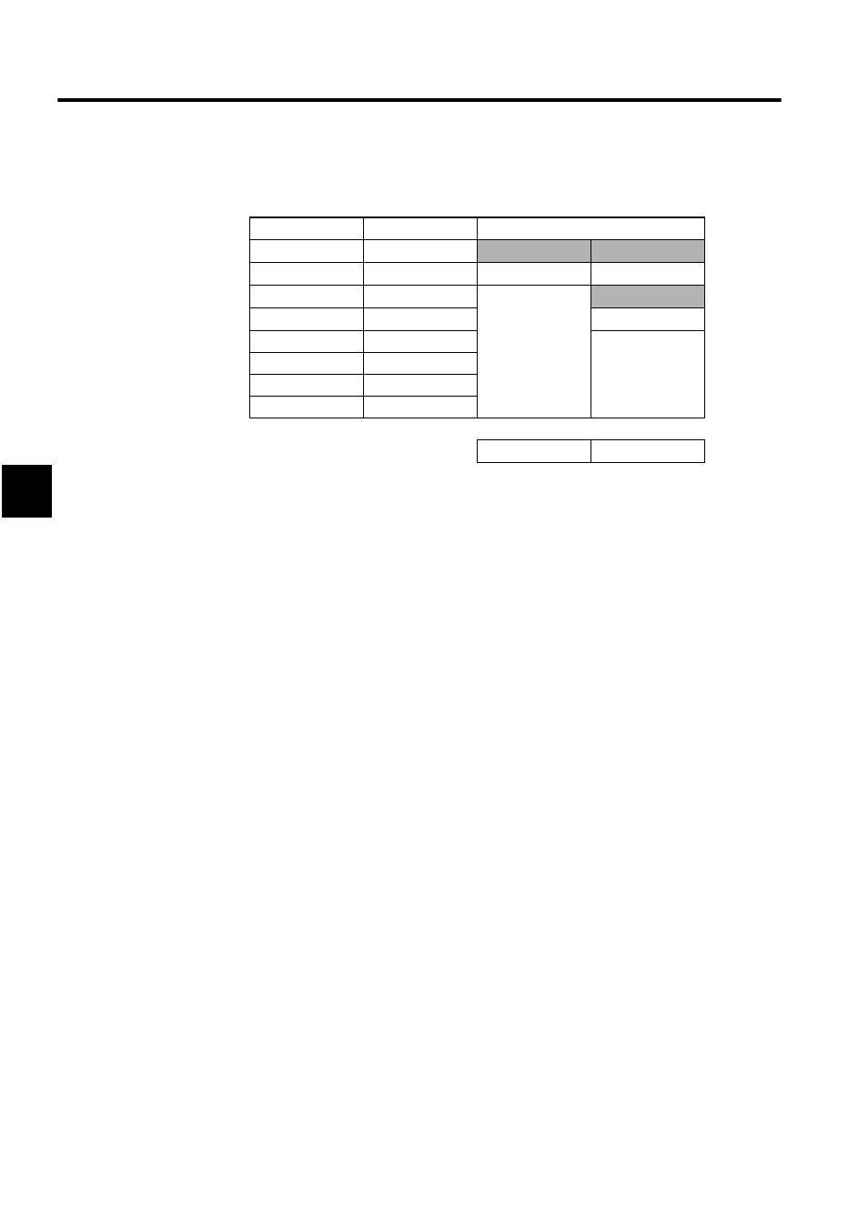
CPU configuration. The CPU configuration can be defined by setting the Modules as
shown in the following table.
b) CPU Rack
Define the MP920 CPU Module in slot number 00 (and 02 for a multiple-CPU con-
figuration) of rack 1 and define other Modules in slot 02 and later slots (slot 04 and
later slots for a multiple-CPU configuration). An error will occur when the settings
are saved in the following cases:
• If a CPU Module is not defined in slot 00 of rack 1.
• If the multiple-CPU configuration has been set in the CP-717 File Manager Win-
dow, but only one CPU Module is set in the Module Configuration Definitions
Window.
c) Other Points
Defined Modules cannot be changed when one of the CPUs in a multiple-CPU con-
figuration is in RUN state, but Modules can be added and deleted. For example, when
a Module such as a 217IF Module is defined in a slot that was occupied by a 215IF
Module, the previous Module's definition data (the 215IF transmission definition
parameters) will be deleted.
2. Control CPU Number Setting and Module Operation
A multiple-CPU configuration requires setting the CPU numbers to control the Mod-
ules.
• Control CPU Number = 1
Control CPU: CPU Module in slot 0 (CPU #1)
Non-Control CPU: CPU Module in slot 2 (CPU #2)
• Control CPU Number = 2
Control CPU: CPU Module in slot 2 (CPU #2)
Non-Control CPU: CPU Module in slot 0 (CPU #1)
a) Module Initialization
The following Modules are initialized by the Control CPU. The non-control CPU
does not perform any initialization processing on any Modules.
Rack Number
Slot Number
MP920
1
00
MP920
MP920
1
01
RESERVED
RESERVED
1
02
Desired Modules
MP920
1
03
RESERVED
1
04
Desired Modules
1
05
1
06
1
07 or greater
Ø
Ø
Single CPU
Multiple CPUs