Yaskawa MP900 Series Machine Controller for Standard Operation User Manual
Page 183
Module Configuration Definitions
3.5.17 SVA Motion Parameters Settings
3-88
3
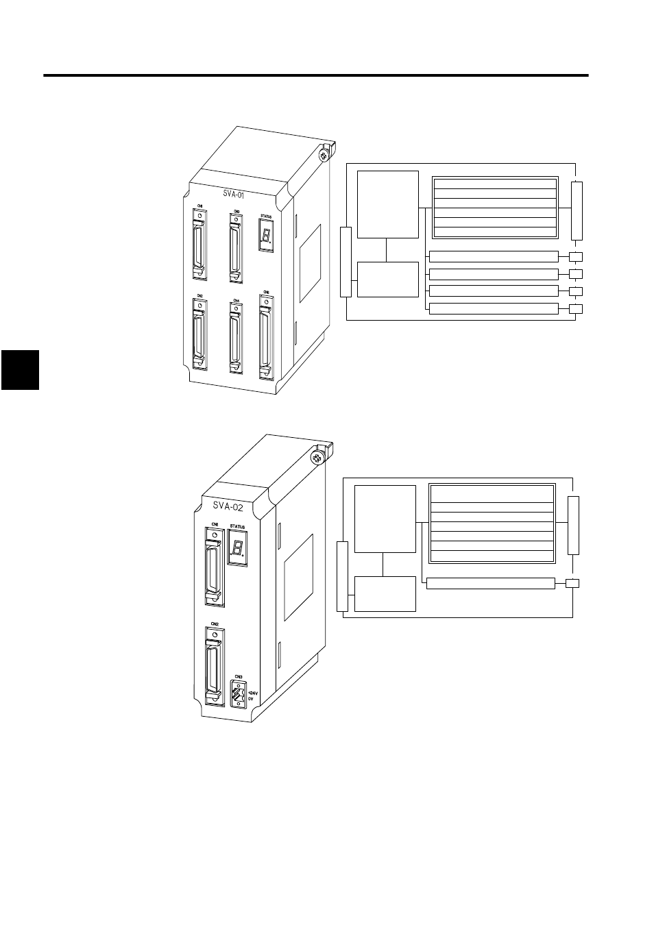
Fig 3.18 SVA-01 Module
Fig 3.19 SVA-02 Module
To set the SVA motion parameters, the required data must be set (or referenced) in three tab
pages: the Fixed Parameters Tab, Set Up Parameters Tab, and Monitor Tab.
The following table lists the basic I/O specifications for the two models of SVA Modules.
CN2
CN3
CN4
CN1
CN5
Analog output: Speed ref.
NREF
Syst
em
Bus Connect
o
r
Motion Control
• Speed control
• Position control
• Phase control
• Zero point return
function
Monitor function
System Bus
Interface
Servo Parameters
• OW
• IW
Pulse input: phase A/B/C
Pulse latch digital input
PIL
3 General-purpose digital inputs
DI0 to D12
6 General-purpose digital outputs
DO0 to DO5
Sensor ON output (5V/24V)
SENS/DO6
Same as above.
Same as above.
Same as above.
External I/O signals
Se
rv
o C
o
nn
ec
tor
CN2
CN1
Syst
em Bus
Connec
tor
System Bus
Interface
Servo Parameters
• OW
• IW
Servo Control
• Speed control
• Position control
• Torque control
• Phase control
• Zero point return
function
Monitor function
2 Analog outputs:Speed ref.
NREF
Positive torque ref.TLIMP
1 Analog input: Speed monitor NREF
Pulse input: phase A/B/C
Pulse latch digital input
PIL
General-purpose digital inputs DI0 to DI5
(5 points + PI latch)
6 General-purpose digital outputs DO0 to DO5
Sensor ON output (5V/24V)SENS/DO6
Same as above.
S
e
rv
o Co
nn
ecto
r