10 mlink (cerf) definitions, Saving, deleting, and closing cntr i/o definitions, B) out data settings – Yaskawa MP900 Series Machine Controller for Standard Operation User Manual
Page 247: Fig 3.27 mlink connections example, Info, Mp940 s#1
Module Configuration Definitions
3.7.10 MLINK (CERF) Definitions
3-152
3
b) OUT Data Settings
Saving, Deleting, and Closing CNTR I/O Definitions
Refer to the procedures in 3.3 Basic Individual Module Definition Operations for details.
The Error Detection Message Box is displayed if the data was not saved successfully. Refer to Appen-
dix A Error Messages, eliminate the cause of the error, and save the data again.
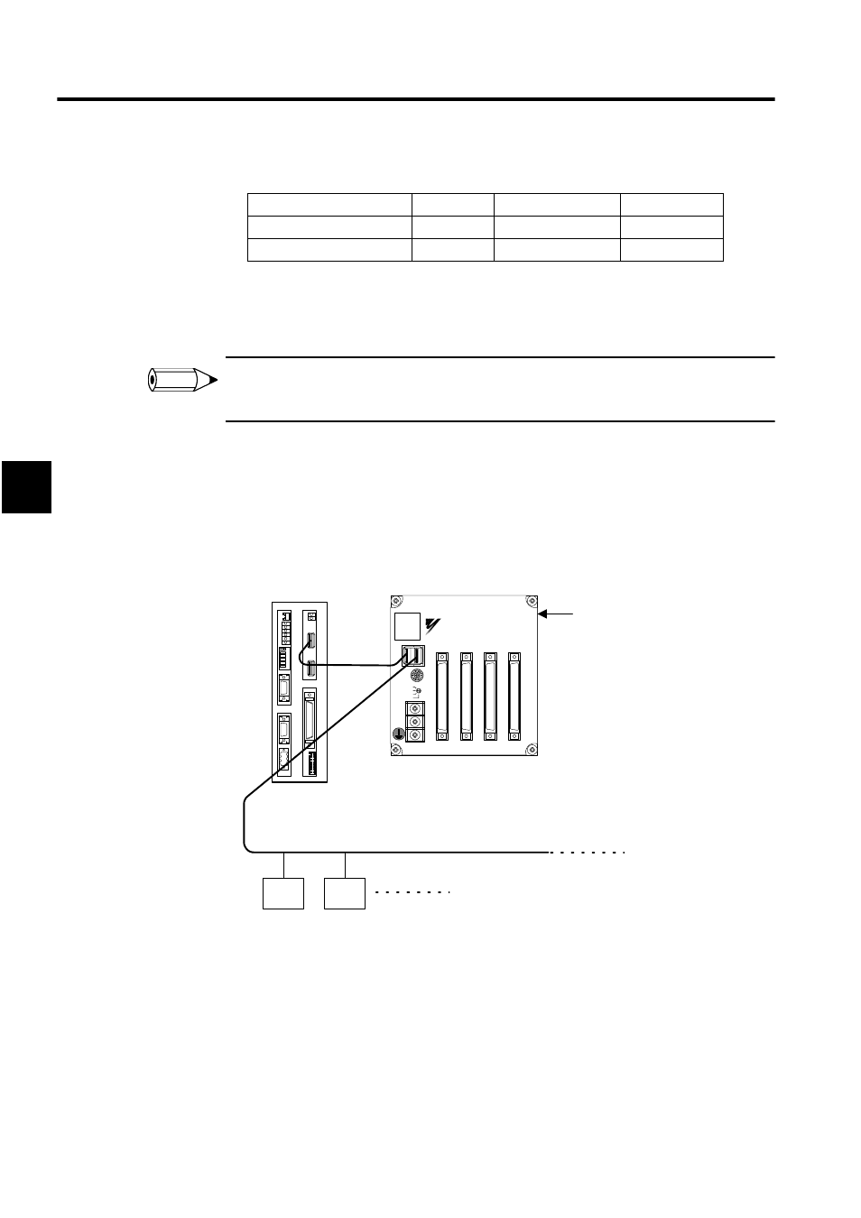
3.7.10 MLINK (CERF) Definitions
To show the concept of the MLINK, the following illustration shows an example of net-
work-compatible I/O Module connections to the MP900-series Machine Controller using the
MECHATROLINK high-speed serial communications.
Fig 3.27 MLINK Connections Example
In this diagram, a Remote I/O Module is connected in station 1 (S#1) and MECHA-
TROLINK I/O Devices are connected from station 2 on.
To set the MLINK parameter, data must be set on the following tab pages: Transmission
Parameters Tab, I/O Assignment Tab, and I/O Map Tab. Communications status can be
checked on the Status Tab Page.
Setting Item
Register
Range
Meaning
Count Preset Data
OL0004
0 to 2147483647
1 = 1 pulse
Set Coincident Detection
OL0006
0 to 2147483647
1 = 1 pulse
INFO
CN1
IN1
OUT1
IN2
OUT2
A1
A1
A1
A1
B1
B1
B1
B1
YASKAWA
JEPMC-IO350
SW1
SW2 IN1
IN2
OUT1
OUT2
DC24V
DC 0V
MP940
S#1
BAT
RDY
RUN
ALM
BAT
PRT1
6
5
4
3
2
1
NO
→
PRT2
RUN
INIT
TEST
FLASH
PP
COPY
PORT1
PORT2
POWER
+24V
GND
FG
LED
I/O
TX
RX
1
2
M
E
C
H
A
T
R
O
L
I
N
K
MP940
S#2
ST#3
I/O Unit
(IO350)
14 stations max.