8 disabling coils – Yaskawa MP900 Series Machine Controller for Standard Operation User Manual
Page 411
Ladder Logic Programming
7.3.8 Disabling Coils
7-44
7
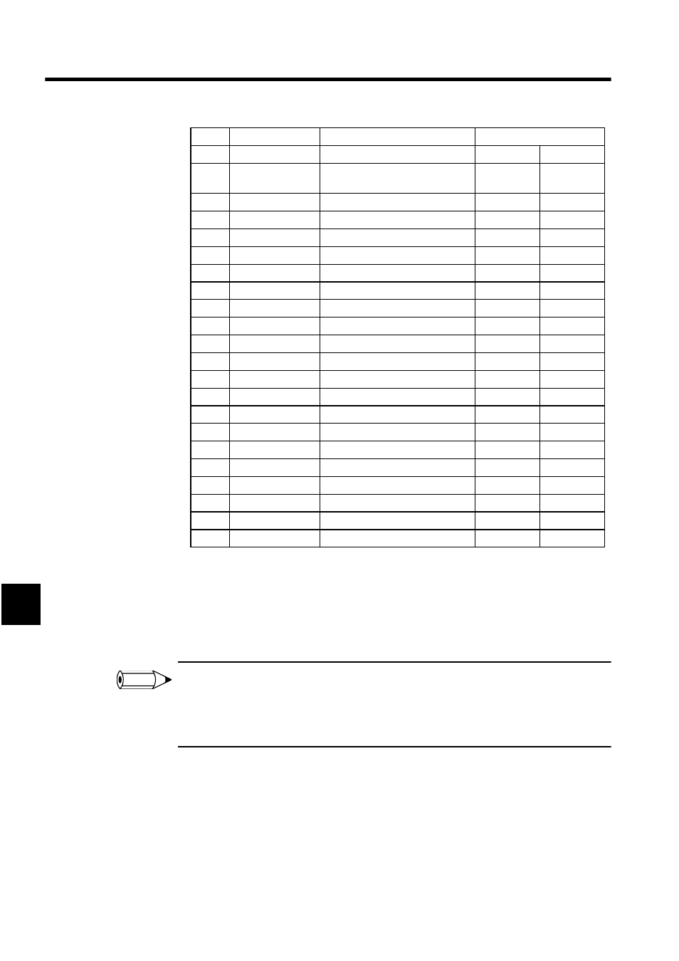
The procedure for step 3 in the table, for example, is outlined below.
1. Select the N.C. CONTACT instruction.
2. Select the BRANCH instruction.
3. Select the connection point.
4. Enter I0000 and press the Enter Key.
1 In step 4., the operand code will determine what type of register is required for the operand. Enter only
the register type and number, and IB00000 will be entered automatically.
2 When multiple operands are used, press the Enter Key after inputting each operand to ensure that each
operand is entered correctly.
7.3.8 Disabling Coils
COIL instructions can be forcibly fixed to the energized state (Disabled ON) or to the de-
energized state (Disabled OFF), and disable settings for COIL instructions can be cleared.
Coil status will be displayed as shown below depending on the disable ON/OFF status.
• COIL Instruction Notation
3
N.C. CONTACT
Branch, connection point
IB00000
4
N.C. CONTACT
Connection point, parallel connec-
tion
IB00001
5
N.O. CONTACT
-
MB000010
6
N.C. CONTACT
Parallel connection
MB000011
7
COIL
Branch
OB00000
8
N.O. CONTACT
Branch
MB00000A
9
N.O. CONTACT
-
MB00000B
10
COIL
-
OB00001
11
N.O. CONTACT
-
MB000002
12
N.C. CONTACT
-
MB000003
13
COIL
-
OB00002
14
N.O. CONTACT
-
IB00100
15
ON PULSE
Branch
DB000000
16
COIL
-
MB000300
17
OFF PULSE
-
DB000001
18
COIL
-
MB000301
19
N.C. CONTACT
-
IB00101
20
ON DELAY
Branch, connection point
5
MW00012
21
N.O. CONTACT
Branch, parallel connection
IB00102
22
COIL
-
OB00100
23
N.O. CONTACT
-
IB00103
24
COIL
-
OB00101
Step
Instruction
Branch or Connection Selection
Operand Input
INFO