Yaskawa MP900 Series Machine Controller for Standard Operation User Manual
Page 396
7.3 Creating Ladder Logic Programs
7-29
7
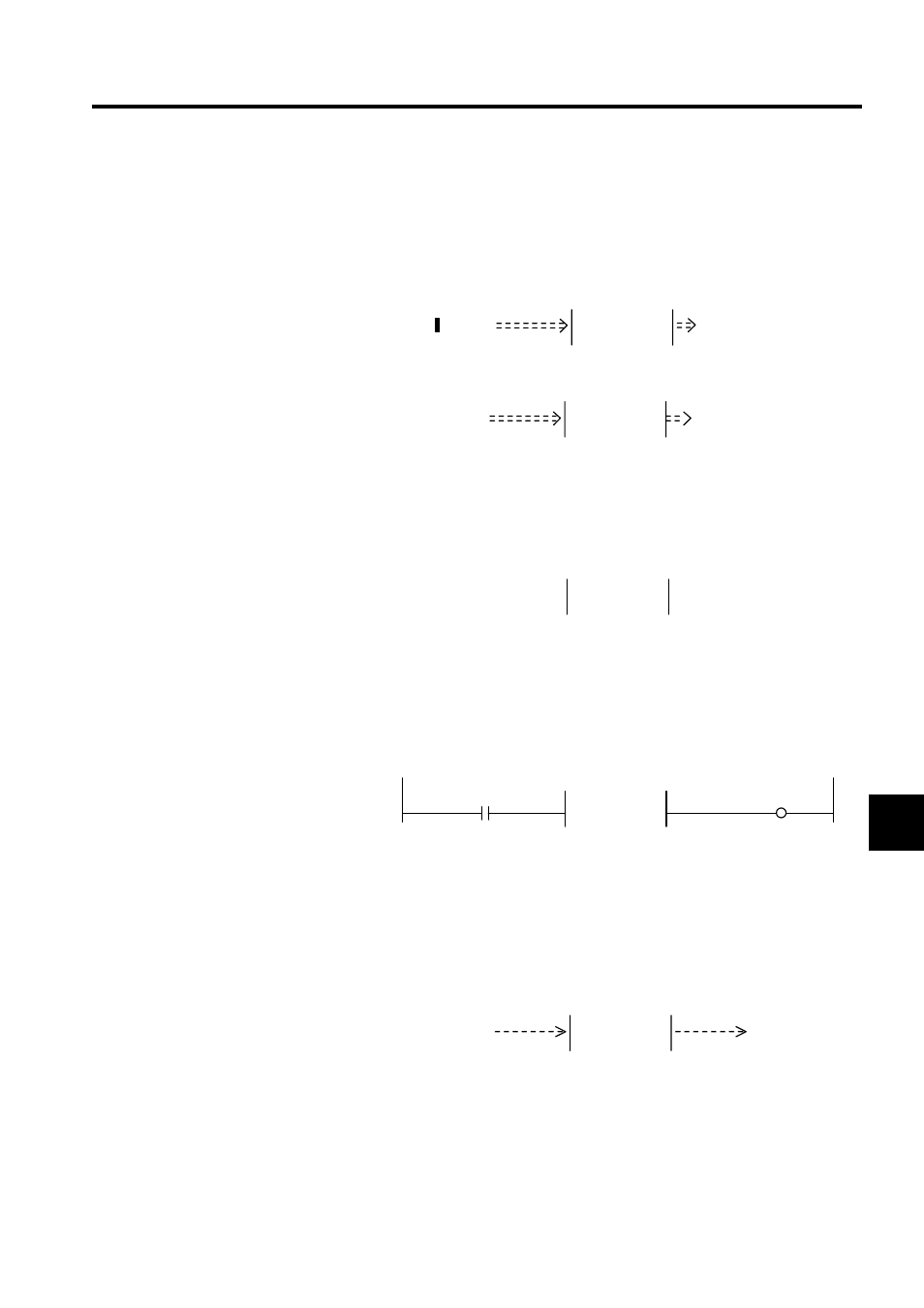
Create the input section for integer data (defined using I-REG), double-length integer
data (defined using L-REG), or real number data (defined using F-REG) as follows:
The following example is for an integer register.
e) Select the FIN instruction. The function input parameters and the register number (or
constant) will be connected.
f) Enter the register number or constant.
3. Address Section
The following example shows how to input addresses,
a) Select the FIN instruction.
b) Enter the register number, MA01000.
4. Entering Outputs
Create the output section for bit data (defined using B-VAL) as follows:
a) Select the FOUT instruction.
b) Enter the COIL instruction and the register number MB000002. The function output
parameters and the COIL instruction will be connected.
Create the output section for integer data (defined using I-VAL), double-length integer
data (defined using L-VAL), or real number data (defined using F-VAL) as follows:
The following example is for an integer register.
c) Select the FOUT instruction.
d) Enter the STORE instruction and the register number, MW00011. The function out-
put parameters and the STORE instruction will be connected.
Create the output section for integer data (defined using I-REG), double-length integer
data (defined using L-REG), or real number data (defined using F-REG) as follows:
The following example is for an integer register.
e) Select the FOUT instruction.
f) Enter the register number, MW00021.
IN-3
OUT-3
FIN
1 0005
IN-3
OUT-3
FIN
1 0005
MW00020
ADDRESS
1 0006
MA01000
1 0001
MB000001
IN-1
OUT-1
FIN
FOUT
MB000002
1 0003
[├ MW00010 ]
⇒
MW00011
IN-2
OUT-2
FIN
FOUT