I/o data set tab page – Yaskawa MP900 Series Machine Controller for Standard Operation User Manual
Page 245
Module Configuration Definitions
3.7.9 CNTR I/O Definitions
3-150
3
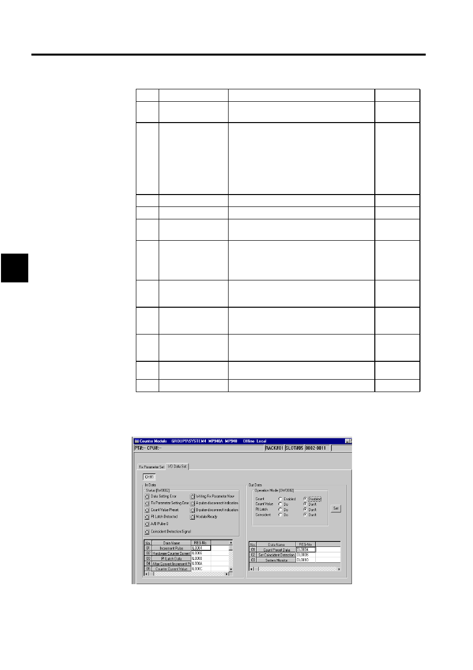
I/O Data Set Tab Page
Click the I/O Data Set Tab.
1. Channel Number
The channel number display is fixed at CH#1.
2
A/B Pulse Signal
Polar
The polarity of the A/B pulse
Positive: 0, Negative: 1
0
3
Pulse Count
0: Signed (multiply x1)
1: Signed (multiply x2)
2: Up/Down (multiply x1)
3: Up/Down (multiply x2)
4: A/B pulse (multiply x1)
5: A/B pulse (multiply x2)
6: A/B pulse (multiply x4)
6
4
Counter Mode
Always set to Reversible Counter.
-
5
PI Latch Detection
Always set to PI Latch.
-
6
Coincident Detec-
tion
Use of coincident detection
Unuse: 0, Use: 1
0
7
Coincident IRQ
Use of coincident interrupt
Unuse: 0, Use: 1
Coincident IRQ is valid only when Coincident
Detection above is set to “1.”
0
8
Select the use of
electronic
gear
Use of gear ratio
Unuse: 0, Use: 1
0
9
Pulse number per
one cycle of
the encoder
1 to 65535
2048
10
Moving amount per
one cycle of
the machine
1 to 2-1
10000
11
Encoder side gear
ratio
1 to 65535
1
12
Gear ratio (load)
1 to 65535
1
No.
Setting Item
Details
Default
- Tag Generator (30 pages)
- MP3300iec (82 pages)
- 1000 Hz High Frequency (18 pages)
- 1000 Series (7 pages)
- PS-A10LB (39 pages)
- iQpump Micro User Manual (300 pages)
- 1000 Series Drive Option - Digital Input (30 pages)
- 1000 Series Drive Option - CANopen (39 pages)
- 1000 Series Drive Option - Analog Monitor (27 pages)
- 1000 Series Drive Option - CANopen Technical Manual (37 pages)
- 1000 Series Drive Option - CC-Link (38 pages)
- 1000 Series Drive Option - CC-Link Technical Manual (36 pages)
- 1000 Series Drive Option - DeviceNet (37 pages)
- 1000 Series Drive Option - DeviceNet Technical Manual (81 pages)
- 1000 Series Drive Option - MECHATROLINK-II (32 pages)
- 1000 Series Drive Option - Digital Output (31 pages)
- 1000 Series Drive Option - MECHATROLINK-II Technical Manual (41 pages)
- 1000 Series Drive Option - Profibus-DP (35 pages)
- AC Drive 1000-Series Option PG-RT3 Motor (36 pages)
- Z1000U HVAC MATRIX Drive Quick Start (378 pages)
- 1000 Series Operator Mounting Kit NEMA Type 4X (20 pages)
- 1000 Series Drive Option - Profibus-DP Technical Manual (44 pages)
- CopyUnitManager (38 pages)
- 1000 Series Option - JVOP-182 Remote LED (58 pages)
- 1000 Series Option - PG-X3 Line Driver (31 pages)
- SI-EN3 Technical Manual (68 pages)
- JVOP-181 (22 pages)
- JVOP-181 USB Copy Unit (2 pages)
- SI-EN3 (54 pages)
- SI-ET3 (49 pages)
- MECHATROLINK-III (35 pages)
- EtherNet/IP (50 pages)
- SI-EM3 (51 pages)
- 1000-Series Option PG-E3 Motor Encoder Feedback (33 pages)
- 1000-Series Option SI-EP3 PROFINET (56 pages)
- PROFINET (62 pages)
- AC Drive 1000-Series Option PG-RT3 Motor (45 pages)
- SI-EP3 PROFINET Technical Manual (53 pages)
- A1000 Drive Option - BACnet MS/TP (48 pages)
- 120 Series I/O Modules (308 pages)
- A1000 12-Pulse (92 pages)
- A1000 Drive Software Technical Manual (16 pages)
- A1000 Quick Start (2 pages)
- JUNMA Series AC SERVOMOTOR (1 page)
- A1000 Option DI-101 120 Vac Digital Input Option (24 pages)