5 i/o definition tab page – Yaskawa MP900 Series Machine Controller for Standard Operation User Manual
Page 375
Ladder Logic Programming
7.2.5 I/O Definition Tab Page
7-8
7
• The number of D and # registers will differ depending on the type of Machine Control-
ler.
• There are some Machine Controller models that will not support the use of SFC pro-
grams. Refer to the MP900 Series Machine Controller User's Manual: Design and
Maintenance.
• The D register numbers that can be used in the program when 10 is input as the number
of D registers are shown in the following table.
The number of words allocated to D and # registers is used for reserving memory. Therefore, when
subscripted registers are used during programming, the programs must be created such that they do not
exceed the memory area set within the program. An operating error will occur when data is read from
or written to a D or # register beyond the set memory area.
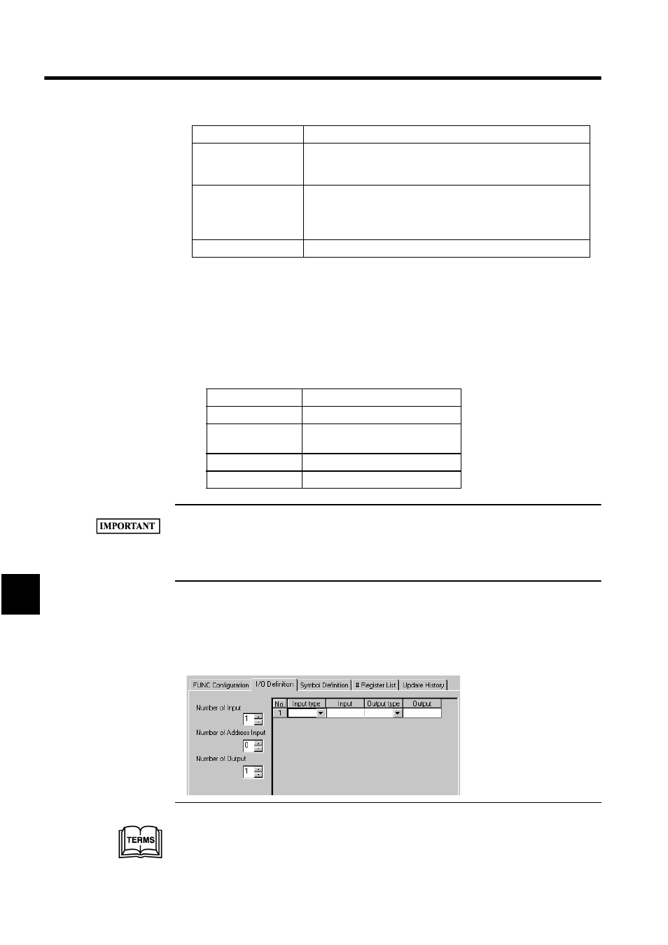
7.2.5 I/O Definition Tab Page
This tab page is used only for function programs. Click the I/O Definition Tab in the Prop-
erty Window.
Number of # Registers
When # registers are to be used by the programs, enter the number of
words for the # registers. # registers cannot be accessed by the pro-
grams if this number is set to 0.
Number of SFC
1
Output Bits
When using SFC within the program, enter the number of output bits
for each SFC step in 16-bit units (maximum 128 bits.) If 0 is entered,
the SFC output bit time chart cannot be displayed, but there is no
effect on the operation of the SFC.
DWG Title
Enter a program title of up to 48 characters.
1 SFC
SFC is the abbreviation for Sequential Function Chart, which is a programming language.
Type
Register Number Range
Integers
DW00000 to DW00009
Double-length
integers
DL00000 to DL00008
Real numbers
DF00000 to DF00008
Bits
DB000000 to DB000009F
Setting Item
Details