Yaskawa MP900 Series Machine Controller for Standard Operation User Manual
Page 160
3.5 MP920 Module Definitions
3-65
3
1. Saving Parameters
When the parameter settings have been completed, save the parameters by selecting File
(F) and then Save (S) from the menu.
2. I/O Allocation Settings Supplementary Explanation
a) Master/Slave Selection and MAC ID Settings
Select the operating mode in Master/Slave Settings to match the 260IF setting switch
SW1 (X1) set value.
Set the DeviceNet address in MAC ID to match the 260IF setting switches SW2 and
SW3 set values.
b) Communications Cycle Settings
Enter the communications cycle time required in 4.2 Calculating Communications
Cycle Times in the MP920 Machine Controller User's Manual: 260IF DeviceNet
(SIEZ-C887-5.2).
This setting is not necessary when using the 260IF as a DeviceNet slave.
c) I/O Allocation
Allocate the I/O registers for sending and receiving I/O data between the Controller
CPU and the 260IF according to the DeviceNet system configuration.
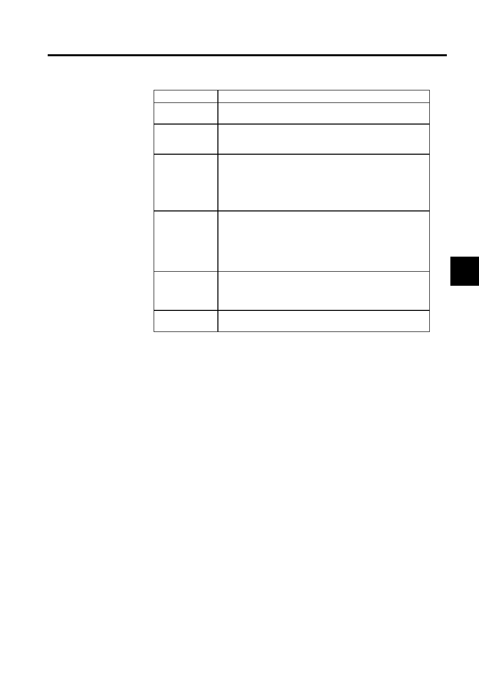
OUTPUT
Set the start address of the output area (output register OWxxxx) allo-
cated to the relevant device. Specify using hexadecimal word address.
BSIZE
Displays in bytes the size of the output area (output register OWxxxx)
allocated to the relevant device. Specify from 1 to 256 (in decimal) for
1 slave. The bytes are little endian, the same as the input registers.
SCAN
The data exchange cycle (SCAN) is the timing for exchanging I/O data
between the Controller CPU and the 260IF. The Controller CPU data
exchange cycle is asynchronous with I/O communications. When set
to high, the Controller CPU exchanges I/O data using the CPU’s high-
speed scan timing. When set to low, the Controller CPU exchanges
data using the CPU’s low-speed scan timing.
TYPE
Set the I/O communications type (TYPE) to Polled or Strobed.
• Polled enables any DeviceNet slaves to be set.
• Strobed enables input only, and limits DeviceNet slaves to commu-
nications of 8 bytes maximum.
For details on polled and strobed connections, refer to the DeviceNet
specifications manual.
EM (Explicit
Message)
Select EM allocation (EM) only when the 260IF is the DeviceNet mas-
ter and message communications are to be performed with the slaves.
DeviceNet slaves performing I/O communications can exchange mes-
sages, but EM allocation setting is not necessary.
COMMENT
A comment of up to 32 characters can be input to include the name,
type, or other information on the relevant device.
Setting Item
Details