Toa N-8000 Series User Manual
Page 80
1-63
Chapter 1
GENERAL DESCRIPTION
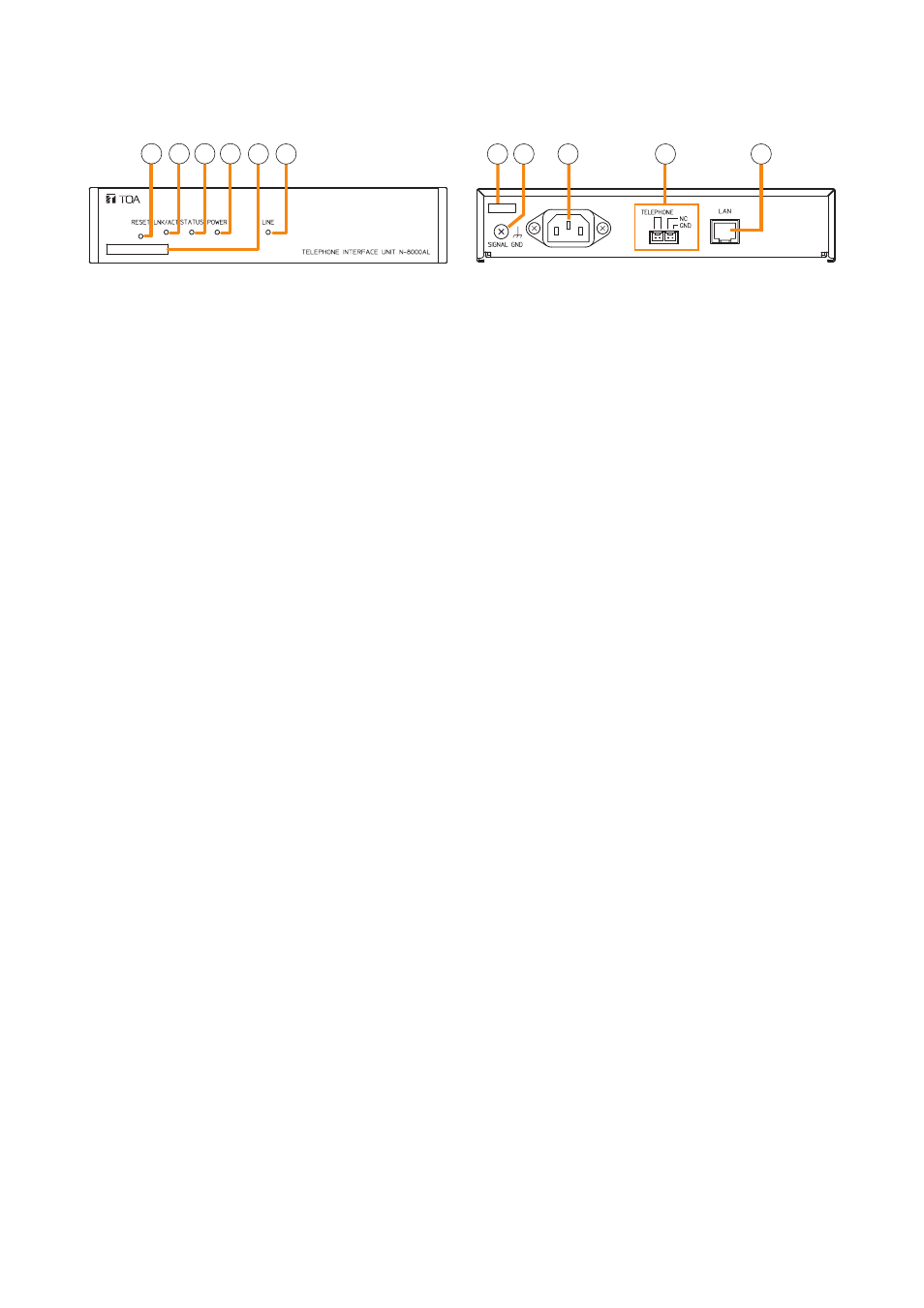
6.4.4. N-8000AL Telephone Interface Unit
1 2 3 4 5 6
7 8
9
10
11
1. Reset key [RESET]
Pressing this key reactivates this unit.
2. LNK/ACT indicator [LNK/ACT] (green)
Lights when connected to a network, and flashes
while transmitting or receiving data.
3. Status indicator [STATUS] (red)
Continuously lights while data is written to an
internal storage medium (FlashMemory).
Flashes if there is a failure. (Refer to
.)
4. Power indicator [POWER] (green)
Lights when power is supplied to the unit.
5. mAC address
This is the MAC address
*1
for the unit. Since the
relationship of each unit location to its MAC address
is established when setting the network attributes,
keep track of this relationship for later use.
*
1
The inherent address assigned to each network
component, expressed in 12-digit hexadecimal
notation.
6. Line indicator [LINE] (green)
Lights when the connected telephone is off-hook.
7. Cord clamp
Pass the power cord through this clamp to ensure
that the plug does not pull out when the unit is
mounted to a wall. (Refer to
.)
8. Functional earth terminal [SIGNAL GND]
Ground this terminal.
Note: This terminal is not for protective earth.
9. AC inlet
Connect the supplied power cord.
Note
If there is a danger of lightning strikes, insert an
appropriate surge arrester into the power line.
10. Telephone connection terminal
[TELEPHONE]
Connect a telephone to this terminal using a mini-
clamp connector. (Refer to
, "Mini-clamp
connector connection.")
11. Network connection terminal [LAN]
Connects to a 10BASE-T- or 100BASE-TX-
compatible network. (Ethernet RJ-45 jack)
[Rear]
[Front]