Toa N-8000 Series User Manual
Page 343
3-39
Chapter 3
INSTALLATION & WIRING
Notes
• When controlling an electronic lock with the N-8050DS/8540DS/8640DS
unit, use "Torx" screws to attach the unit at installation so that it cannot be
detached easily.
• For the N-8050DS installation, be sure to ground the YC-150 or electrical
box.
For the N-8540DS installation, be sure to ground the YC-150, electrical box,
or the frame ground terminal on the unit's rear (
• For the N-8640DS installation, be sure to ground both the YC-150 or electrical
box, and the frame ground terminal on the unit's rear (
).
• When installing the unit at outdoor or locations where it gets wet with water,
tightly seal the panel edges. Besides, provide a weep hole at the underside
of the mounting box to permit water to drain off.
• When installing the N-8050DS/8540DS under difficult environmental
conditions such as in coastal areas or at humid locations, cover the inside
of the N-8050DS/8540DS with coating. For the coating method, consult your
TOA dealer.
• Treat unused cables so as not to short-circuit. (N-8640DS only)
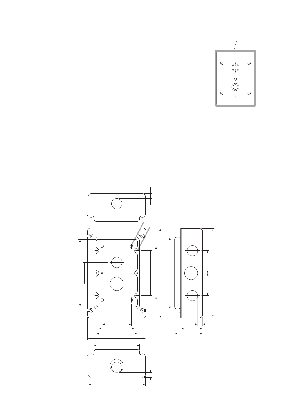
Seal the panel edges.
The figure represents
N-8500DS/8540DS's front panel.
[YC-150 dimensional drawing]
138
57
44
10
182
147
184
11
0
46
10
117
93
119
83.5
73
60
44
10
46
46
46
Dimension of knockout hole
A: φ21.5
B: φ27.1
4-φ6
6-M4
B
B
B
A
A
A
A
Unit: mm