Toa N-8000 Series User Manual
Page 78
1-61
Chapter 1
GENERAL DESCRIPTION
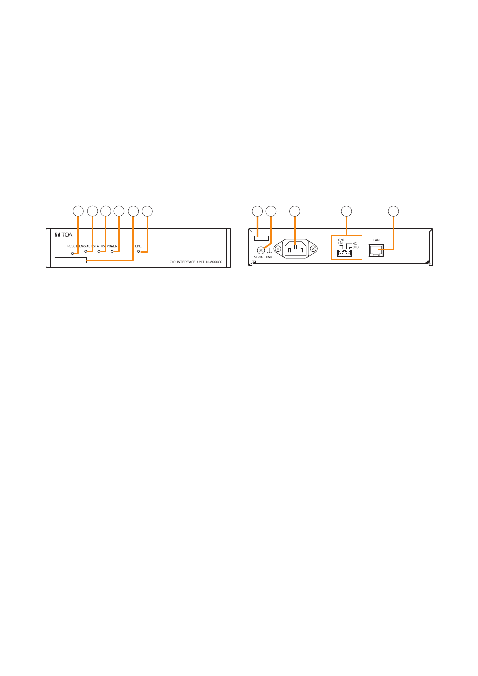
6.4.2. N-8000CO C/O Interface Unit
1 2 3 4 5 6
7 8
9
10
11
1. Reset key [RESET]
Pressing this key reactivates this unit.
2. LNK/ACT indicator [LNK/ACT] (green)
Lights when connected to a network, and flashes
while transmitting or receiving data.
3. Status indicator [STATUS] (red)
Continuously lights while data is written to an
internal storage medium (FlashMemory).
Flashes if there is a failure. (Refer to
.)
4. Power indicator [POWER] (green)
Lights when power is supplied to the unit.
5. mAC address
This is the MAC address*
1
for the unit. Since the
relationship of each unit location to its MAC address
is established when setting the network attributes,
keep track of this relationship for later use.
*
1
The inherent address assigned to each network
component, expressed in 12-digit hexadecimal
notation.
6. Outside line indicator [LINE] (green)
Remains lit while accessing the outside line.
7. Cord clamp
Pass the power cord through this clamp to ensure
that the plug does not pull out when the unit is
mounted to a wall. (Refer to
.)
8. Functional earth terminal [SIGNAL GND]
Ground this terminal.
Note: This terminal is not for protective earth.
9. AC inlet
Connect the supplied power cord.
Note
If there is a danger of lightning strikes, insert an
appropriate surge arrester into the power line.
10. Outside Line Connection Terminal
[C/O LINE]
Connect the outside line to this terminal using a
mini-clamp connector. (Refer to
, "Mini-
clamp connector connection.")
11. Network connection terminal [LAN]
Connects to a 10BASE-T- or 100BASE-TX-
compatible network. (Ethernet RJ-45 jack)
13. Audio output terminal [AuDIO OuT]
Includes audio outputs (maximum 0 dB
*2
, under
600 Ω, balanced) and control outputs (relay
contact withstand voltage: 24 V DC, control
current: maximum 0.5 A).
Each control output remains closed during audio
signal output.
Connect using a removable terminal plug.
(Refer to
, "Terminal plug connection.")
14. PBX interface terminal [PBX IF]
Connects to the Exchange of the EXES-2000
or EXES-6000 system by a tie-line, or the PBX
exchange via the analog E&M interface.
15. Network connection terminal [10/100M]
Connects to a 10BASE-T- or 100BASE-TX-
compatible network. (Ethernet RJ-45 jack)
*
2
0 dB = 1 V
[Rear]
[Front]