Unit scan and broadcast communications domains, P. 8-9, Sampling frequency correction – Toa N-8000 Series User Manual
Page 609
8-9
Chapter 8
APPENDIX
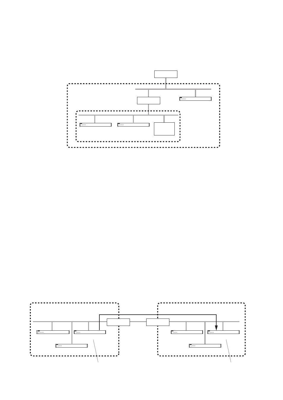
In the above figure, NET 1 represents a network, while NET 2 is the valid broadcasting range. In this example,
if the PC performs equipment detection, it will not be able to detect Equipment C despite its location within the
same local area network.
Consult your network administrator regarding the valid broadcast range.
2.6. Sampling Frequency Correction
(N-8000EX/8010EX/8000MI only)
This function is used to correct and synchronize the operating clocks for all exchanges and multi interface units
on the system to the same value. Failure to synchronize operating clocks in this way may result in word dropout
during broadcasts over two minutes.
By default, automatic correction is enabled for equipment within the above broadcast domain. To correct sampling
frequencies between equipment connected to different networks divided by a router or other equipment (for
example "Network A" and "Network B"), first correct the sampling frequency setting for one of the exchanges
or multi interface units connected to Network A, and designate the IP address of one of the exchanges or
multi interface units connected to Network B as a corrected data transmission destination, then perform the
correction data receiving setting for that Network B exchange. When Router B is using NAT, designate the
global IP address of Router B as a corrected data transmission destination.
The number of destinations to which correction data can be transferred to is limited to 16 total for unicast and
multicast combined.
2.5. Unit Scan and Broadcast Communications Domains
The broadcast communications method is utilized to detect equipment (exchange, any kind of interface unit,
or IP station) connected to a network. Therefore, only equipment within the network's multicasting range
will be detected. This range is called the "broadcast domain." The broadcast address used for detection is
255.255.255.255. Normally, a broadcast packet does not reach beyond a router, even within a local area
network.
Network A
Network B
Router B
Router A
"Transmission to the N-8000EX (F)" setting
(Automatic correction within the network)
(Automatic correction within the network)
"Reception from the N-8000EX (C)" setting
N-8000EX (A)
N-8000MI (B)
N-8000EX (C)
N-8000EX (D)
N-8000MI (E)
N-8000EX (F)
Router
Router
PC
NET1
NET2
N-8000MI (B)
N-8000EX (A)
N-8000EX (C)