Toa N-8000 Series User Manual
Page 61
1-44
Chapter 1
GENERAL DESCRIPTION
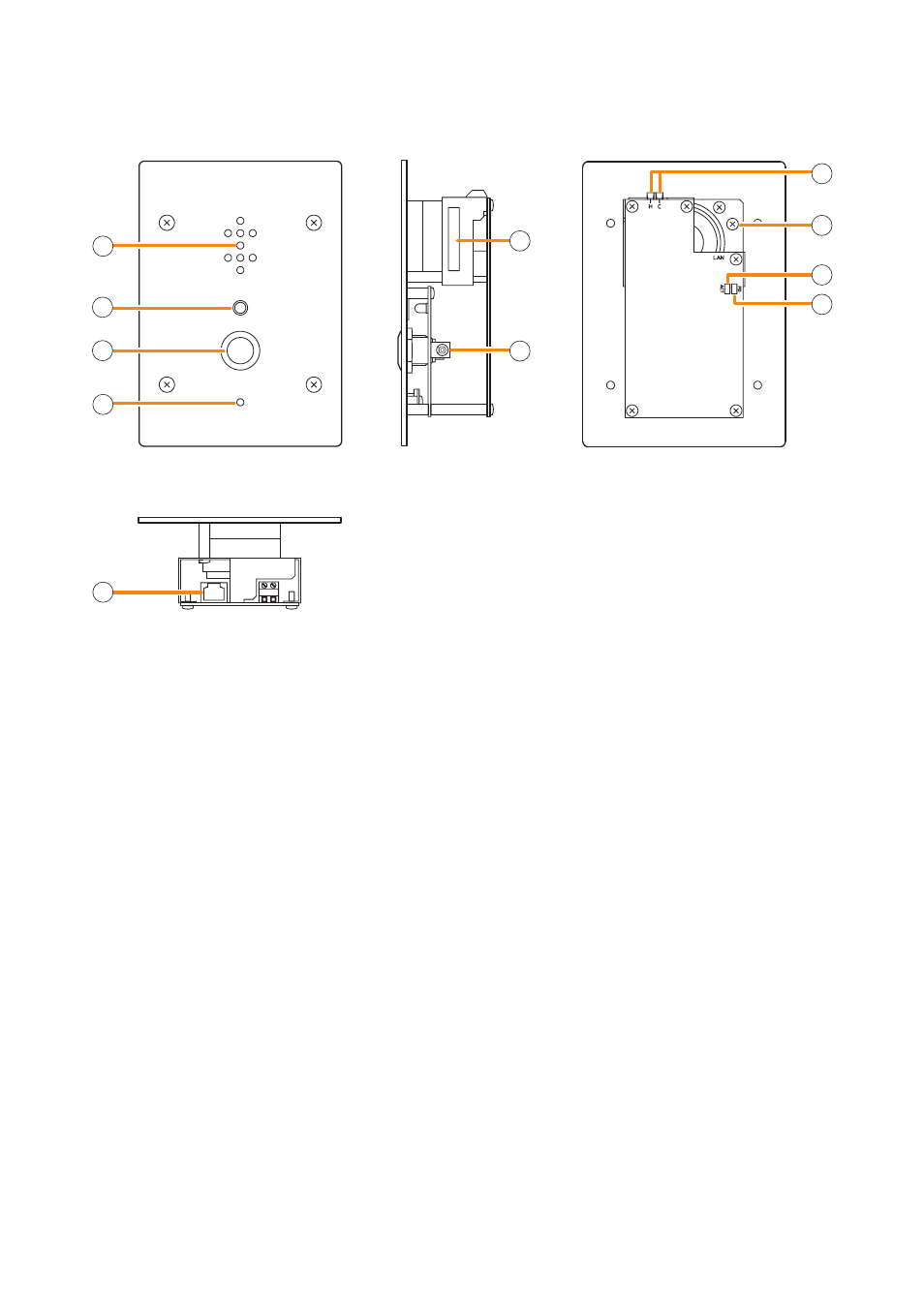
6.2.5. N-8540DS IP Door Station
1. Speaker
Outputs call tones and used for hands-free
conversations.
2. Status indicator (red)
Flashes when a call or paging announcement is
received, continuously lights during conversation,
and is off while in standby mode. The indicator
also continuously lights while data is written to
an internal storage memory (FlashMemory), and
flashes if there is a failure.
(Refer to
3. Call button
Used to call the preprogrammed master station.
4. microphone
Used for hands-free conversation.
5. mAC address
This is the MAC address* for the unit. Since the
relationship of each unit location to its MAC address
is established when setting the network attributes,
keep track of this relationship for later use.
* The inherent address assigned to each network
component, expressed in 12-digit hexadecimal
notation.
6. AC adapter terminal
Connect the AC adapter* to this terminal.
*
Use the AD-1210P/1215P (optional) or its
equivalent.
7. Contact output terminals [H, C]
External equipment such as an electronic lock
can be connected.
(Output capacity: 30 V DC and 50 mA)
(Refer to
.)
8. Frame ground terminal (FG)
Ground from this terminal when the switch box is
not grounded.
9. ACT indicator (green)
Lights while transmitting or receiving data.
10. FD indicator (yellow)
Lights when the network is in full duplex
communications.
11. Network connection terminal [PC]
Can be connected to a network of 10BASE-
T/100BASE-TX in auto-sensing.
Connecting the station to a PoE (Power over
Ethernet) switching hub eliminates the need for
an AC adapter.
(Ethernet RJ-45 jack)
2
1
3
4
5
6
7
8
9
10
11
[Top]
[Rear]
[Front]
[Side]