Example of a gre ip tunnel configuration – Brocade Multi-Service IronWare Switching Configuration Guide (Supporting R05.6.00) User Manual
Page 748
718
Multi-Service IronWare Switching Configuration Guide
53-1003036-02
GRE IP tunnel
19
Configuring a maximum MTU value for a tunnel interface
You can set an MTU value for packets entering the tunnel. Packets that exceed either the default
MTU value of 1476 bytes or the value that you set using this command are fragmented for transit
through the tunnel. The default MTU value is set to 1476.
The following command allows you to change the MTU value for packets transiting “tunnel 1”.
Brocade(config)# interface tunnel 1
Brocade(config-tnif-1)tunnel mtu 1500
Syntax: [no] tunnel mtu packet-size
The packet-size variable specifies the maximum MTU size in bytes for the packets transiting the
tunnel.
NOTE
To prevent packet loss after the 24 byte GRE header is added, make sure that any physical interface
that is carrying GRE tunnel traffic has an IP MTU setting at least 24 bytes greater than the tunnel
MTU setting.
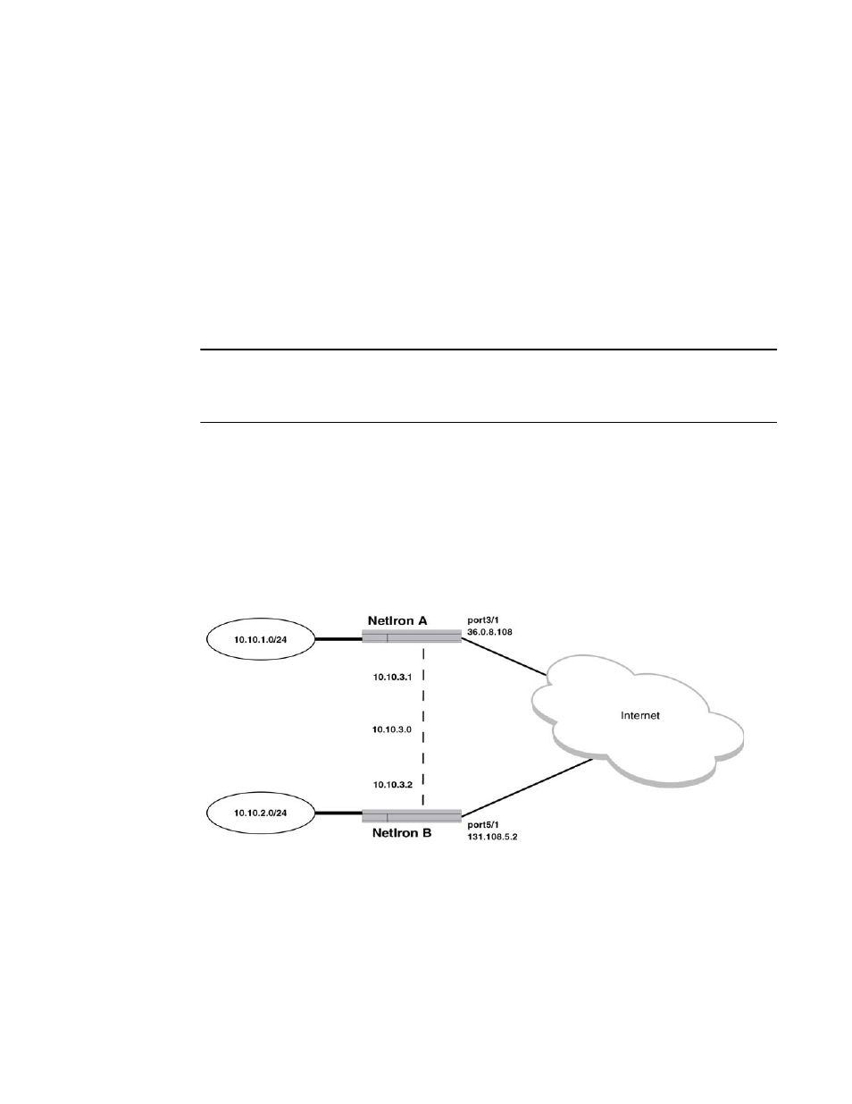
Example of a GRE IP tunnel configuration
In this example, a GRE IP Tunnel is configured between the Brocade A device and the Brocade B
device. Traffic between networks 10.10.1.0/24 and 10.10.2.0/24 is encapsulated in a GRE IP
packet sent through the tunnel on the 10.10.3.0 network. and unpacked and sent the destination
network. A static route is configured at each device to go through the tunnel interface to the target
network.
FIGURE 189
GRE IP tunnel configuration example
Configuration example for Brocade A
Brocade(config)# interface ethernet 3/1
Brocade(config-int-e10000-3/1)# ip address 36.0.8.108/24
Brocade(config)# interface tunnel 1
Brocade(config-tnif-1)# tunnel source 36.0.8.108
Brocade(config-tnif-1)# tunnel destination 131.108.5.2
Brocade(config-tnif-1)# tunnel mode gre ip