Convergence in a simple topology, Convergence at start up – Brocade Multi-Service IronWare Switching Configuration Guide (Supporting R05.6.00) User Manual
Page 453
Multi-Service IronWare Switching Configuration Guide
423
53-1003036-02
Convergence in a simple topology
13
Convergence in a simple topology
The examples in this section illustrate how RSTP convergence occurs in a simple Layer 2 topology
at start-up.
NOTE
The remaining examples assume that the appropriate handshake mechanisms occur as port roles
and states change.
Convergence at start up
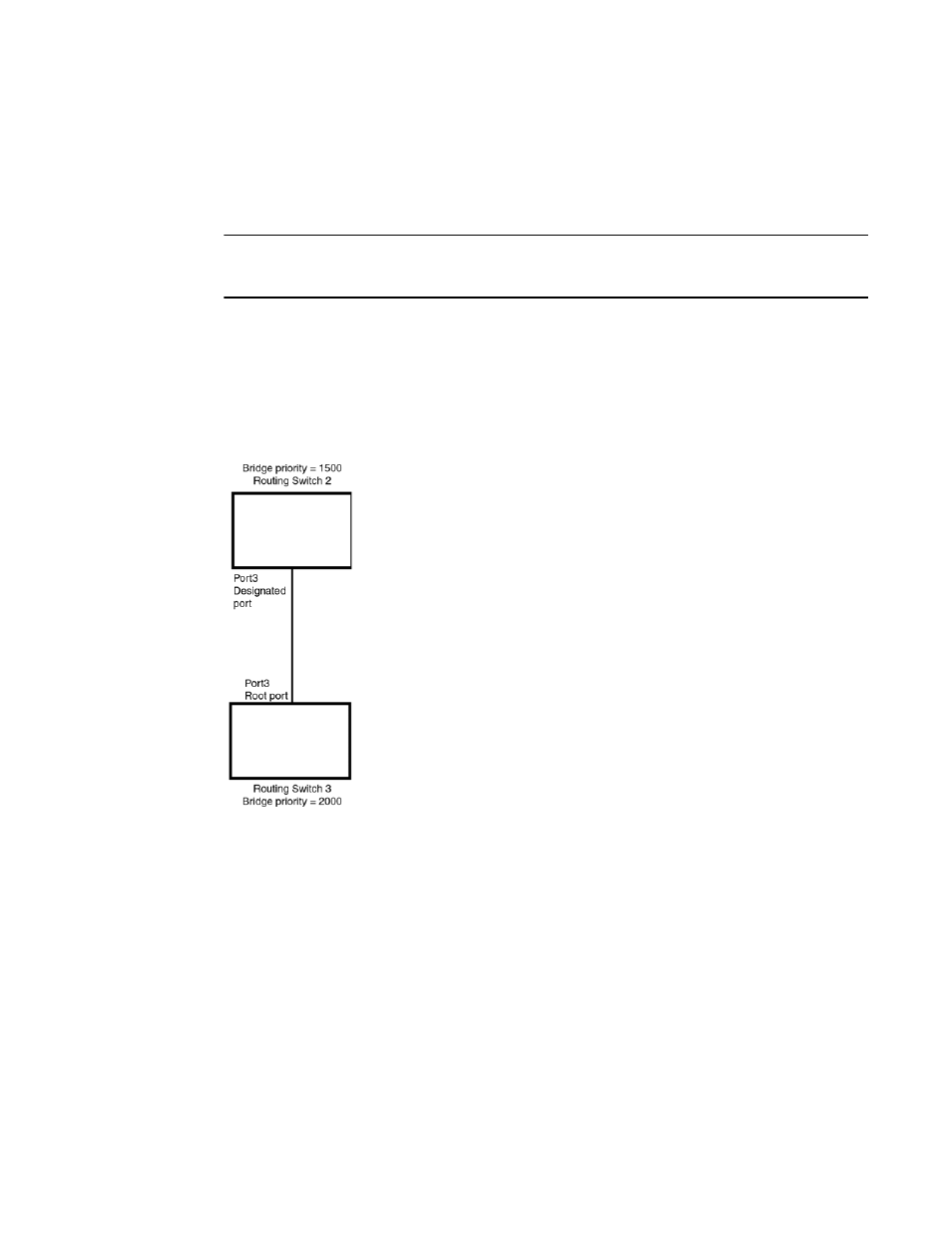
In
, two bridges Switch 2 and Switch 3 are powered up. There are point-to-point
connections between Port3/Switch 2 and Port3/Switch 3.
FIGURE 85
Convergence between two bridges
At power up, all ports on Switch 2 and Switch 3 assume Designated port roles and are at discarding
states before they receive any RST BPDU.
Port3/Switch 2, with a Designated role, transmits an RST BPDU with a proposal flag to
Port3/Switch 3. A ports with a Designated role sends the proposal flag in its RST BPDU when they
are ready to move to a forwarding state.
Port3/Switch 3, which starts with a role of Designated port, receives the RST BPDU and finds that it
is superior to what it can transmit; therefore, Port3/Switch 3 assumes a new port role, that of a
Root port. Port3/Switch 3 transmits an RST BPDU with an agreed flag back to Switch 2 and
immediately goes into a forwarding state.
Port3/Switch 2 receives the RST BPDU from Port3/Switch 3 and immediately goes into a
forwarding state.
Now RSTP has fully converged between the two bridges, with Port3/Switch 3 as an operational root
port in forwarding state and Port3/Switch 2 as an operational Designated port in forwarding state.
Next, Switch 1 is powered up (