Convergence in a complex rstp topology – Brocade Multi-Service IronWare Switching Configuration Guide (Supporting R05.6.00) User Manual
Page 458
428
Multi-Service IronWare Switching Configuration Guide
53-1003036-02
Convergence in a complex RSTP topology
13
Convergence in a complex RSTP topology
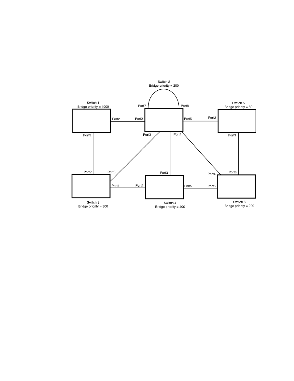
The following is an example of a complex RSTP topology.
FIGURE 89
Complex RSTP topology
In
, Switch 5 is selected as the root bridge since it is the bridge with the highest priority.
Lines in the figure show the point-to-point connection to the bridges in the topology.
Switch 5 sends an RST BPDU that contains a proposal flag to Port5/Switch 2. When handshakes
are completed in Switch 5, Port5/Switch 2 is selected as the Root port on Switch 2. All other ports
on Switch 2 are given Designated port role with discarding states.
Port5/Switch 2 then sends an RST BPDU with an agreed flag to Switch 5 to confirm that it is the
new Root port and the port enters a forwarding state. Port7 and Port8 are informed of the identity
of the new Root port. RSTP algorithm selects Port7 as the Designated port while Port8 becomes
the Backup port.
Port3/Switch 5 sends an RST BPDU to Port3/Switch 6 with a proposal flag. When Port3/Switch 5
receives the RST BPDU, handshake mechanisms select Port3 as the Root port of Switch 6. All other
ports are given a Designated port role with discarding states. Port3/Switch 6 then sends an RST
BPDU with an agreed flag to Port3/Switch 5 to confirm that it is the Root port. The Root port then
goes into a forwarding state.
Now, Port4/Switch 6 receives RST BPDUs that are superior to what it can transmit; therefore, it is
given the Alternate port role. The port remains in discarding state.
Port5/Switch 6 receives RST BPDUs that are inferior to what it can transmit. The port is then given
a Designated port role.