Edge rstp – Brocade Multi-Service IronWare Switching Configuration Guide (Supporting R05.6.00) User Manual
Page 484
454
Multi-Service IronWare Switching Configuration Guide
53-1003036-02
RSTP support for PB and PBB
13
Configuring CE-2
C-VLAN Configuration
Configure a regular Layer 2 VLAN with 400 (C-VLAN) and add port 1/4 to it.
Brocade_CE-2(config)#vlan 400
Brocade_CE-2(config-vlan-400)#tagged ethernet 1/4
Configuring RSTP on CE-1 and CE-2
RSTP Configuration
Brocade_CE-1(config)#vlan 400
Brocade_CE-1(config-vlan-400)#rstp
Use case 3: Edge RSTP - AS-1 is connected to AS-2 via IB-tagged endpoint and
both the AS on ES facing side with same S-VLAN
The following deployment scenario is a case where RSTP is deployed on a VPLS instance which has
a S-VLAN configured to the ES facing side and B-VLAN configured which connects 2 ASs.
AS-1 is configured as a ROOT Bridge and RSTP is running on the VPLS Instance on AS-1, AS-2 and
ES-1. VPLS VLAN 200 is configured in AS-1 and AS-2 acts as B-VLAN which connects AS-1 and
AS-2. VPLS VLAN 300 is configured in AS-1 and AS-2 acts as S-VLAN which connects AS-1 and AS-2
to the ES-1. In AS-1 and AS-2 VPLS VLAN 200 and 300 are configured under the same VPLS
instance. VPLS VLAN 300 (S-VLAN) is configured on ES-1, which connects to AS-1 and AS-2.
The following discussion describes how to configure the nodes in the topology.
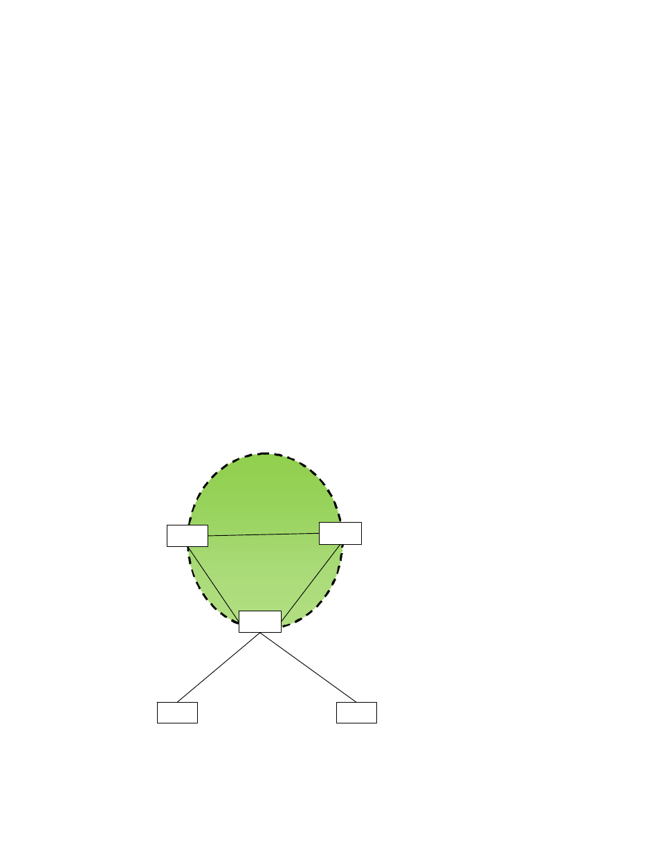
FIGURE 100
Edge RSTP topology 3
AS‐2
ES‐1
AS‐1
Edge RSTP
CE‐1
CE‐2
1/2
S‐VLAN 300
1/3
S‐VLAN 300
1/3
1/1
1/1
1/4
1/4
1/2
1/1 B‐ VLAN 200
1/1