Brocade Multi-Service IronWare Switching Configuration Guide (Supporting R05.6.00) User Manual
Page 369
Multi-Service IronWare Switching Configuration Guide
339
53-1003036-02
SuperSpan™
12
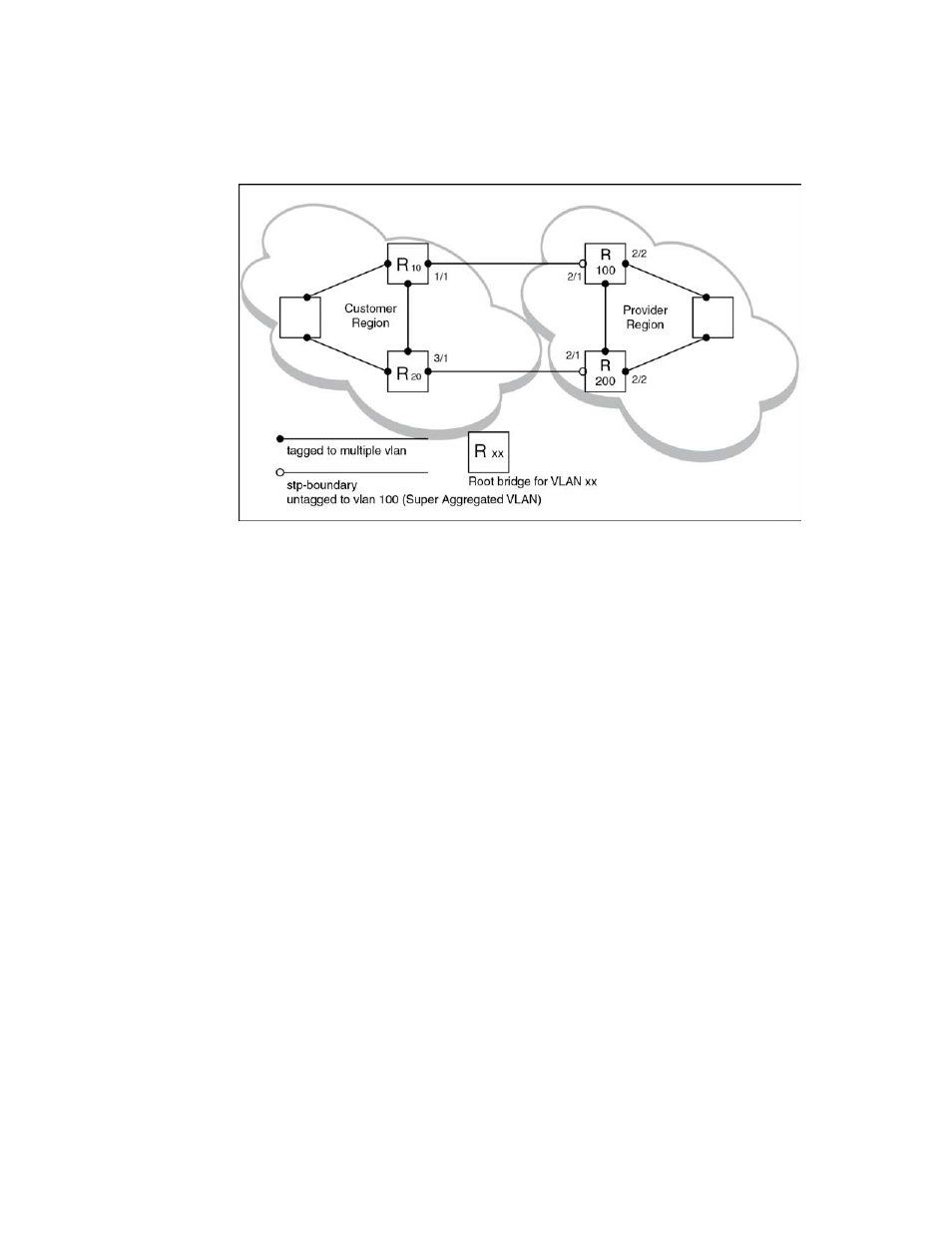
FIGURE 59
Customer and SP using multiple spanning trees
Both the customer and SP regions are running multiple spanning trees (one per port-based VLAN)
in the Layer 2 switched network. The customer network contains VLANs 10 and 20 while the SP
network contains VLANs 100 and 200. Customer traffic from VLAN 10 and VLAN 20 is aggregated
by VLAN 100 in the SP since the boundary ports, 2/1 on R100 and R200, are untagged members
of VLAN 100. By adjusting the bridge priority on VLANs 10 and 20, the customer can select a
different root bridge for each spanning tree running in the customer network.
In the above example, STP in VLAN 10 will select R10 as the root bridge and make 1/1 on R10
forwarding while blocking port 3/1 on R20. The opposite occurs for STP in VLAN 20. As a result,
both links connecting the customer and SP regions are fully utilized and serve as backup links at
the same time, providing loop-free, non-blocking connectivity. In the SP network, multiple STP
instances are running (one for VLAN 100 and one for VLAN 200) to ensure loop-free, non-blocking
connectivity in each VLAN.
SuperSPAN boundaries are configured at port 2/1 of R100 and R200. Since the customer’s traffic
will be aggregated into VLAN 100 at the SP, the SP network appears to the customer to be a
loop-free non-blocking hub to the customer network when port 2/2 on R200 is blocked by STP in
VLAN 100.