Brocade Multi-Service IronWare Switching Configuration Guide (Supporting R05.6.00) User Manual
Page 512
482
Multi-Service IronWare Switching Configuration Guide
53-1003036-02
How ring breaks are detected and healed
14
NOTE
In the event of a shared interface failing the alarm RHP packet is only sent by the owner ring of the
failed interface. If all rings configured on a shared interface were to generate alarms then the
respective master switches for each ring would start forwarding on both interfaces creating a loop
condition. By restricting alarm generation to the owner ring we ensure that only one master switch
is notified to ensure that the ring heals. The owner ring ID should be the highest priority ring
configured on the shared interface.
Operation of the alarm RHP enhancement is shown in
and described below:
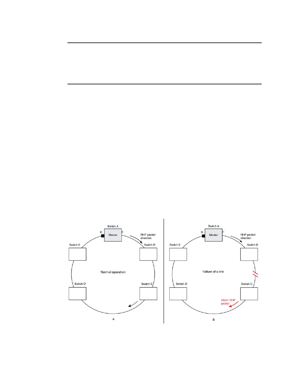
When the link between Switch B and Switch C fails, the downstream switch detects the failure of
the link associated with its secondary ring interface and generates an alarm. The following is the
complete sequence of events that occurs.
1. The downstream Switch C detects a link down event on the link to its upstream neighbor
Switch B.
2. Switch C sends a single RHP packet with the alarm bit set. The RHP packet is sent in the same
direction of flow as that of the normal RHP packets.
3. Switch A receives the alarm on the secondary ring interface that was sent by Switch C. It is now
aware that the ring is broken even though the preforwarding timer for blocking to preforwarding
may not have expired.
4. Switch A immediately transitions its secondary interface from blocking to forwarding to heal
the ring.
5. RHP packets continue to be sent on the primary interface by Switch A to detect when the ring
has been healed.
From a user perspective there is no other difference in the behavior of the ring other than the rapid
convergence due to link failures. There is no CLI command required to enable this feature.
FIGURE 110
An MRP ring under normal operation (A) and after detection of a failure in the ring (B)