Ring interface ownership – Brocade Multi-Service IronWare Switching Configuration Guide (Supporting R05.6.00) User Manual
Page 521
Multi-Service IronWare Switching Configuration Guide
491
53-1003036-02
MRP Phase 2
14
It is very easy to focus on the ring topology rather than the underlying layer 2 topology described by
multiple rings. Design decisions are driven by the same factors as a standard spanning tree
network replacing root bridges with ring masters. Traffic patterns at layer 2 are determined by
which ring interfaces are forwarding and which are blocking and this in turn should drive design
decisions for ring master placement as well as the direction of RHP flow from the ring masters.
Traffic patterns in standard operation as well as failure mode can be determined prior to
implementation allowing for appropriate capacity management on all links.
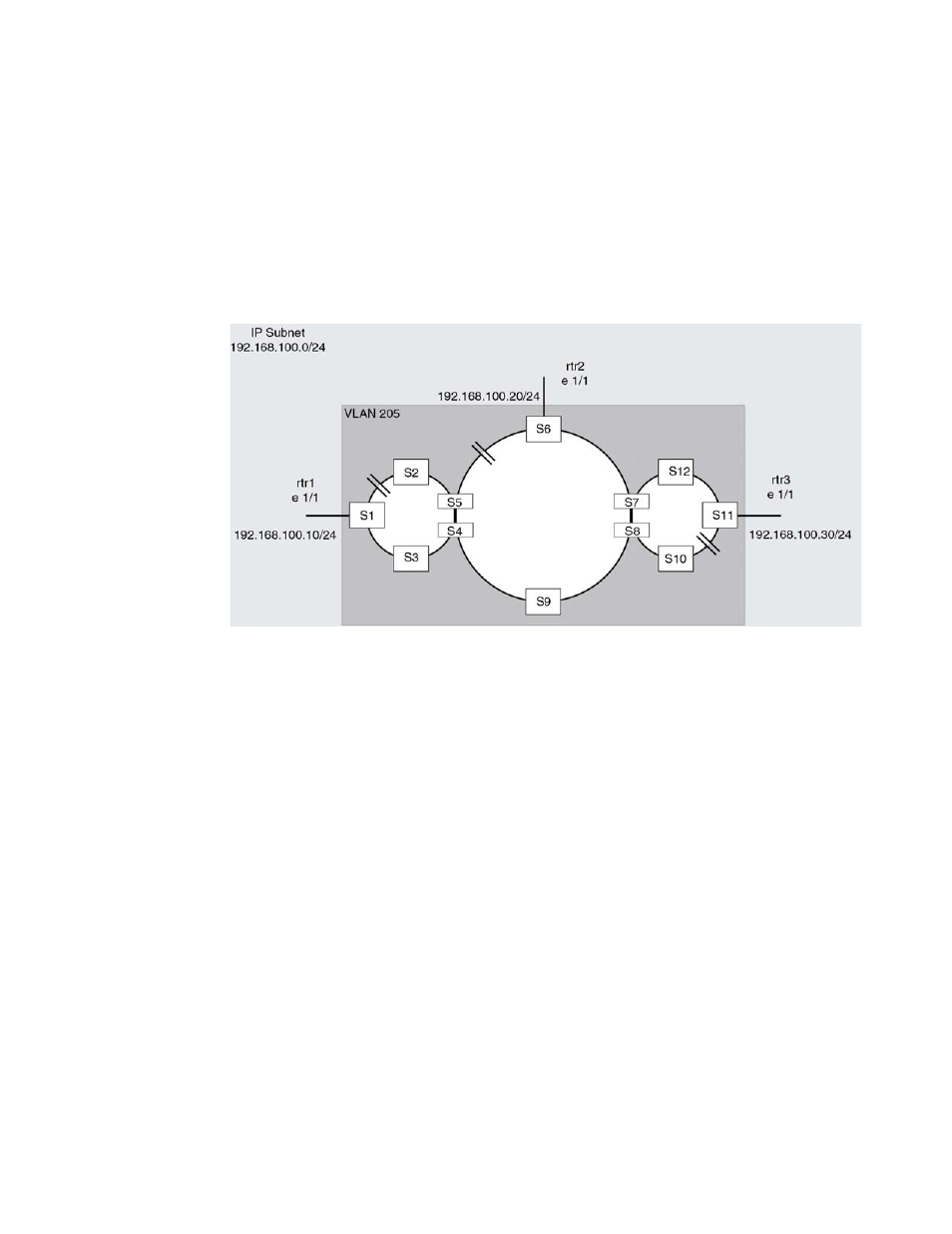
FIGURE 116
Multiple rings with one vlan spanning them
Ring interface ownership
On a shared interface the highest priority ring will be the owner of the interface. In
interface e 1/1 on S1 will be owned by ring 1 and marked as a regular interface while in ring 2 the
same interface is marked as a tunnel interface in the output of the ‘show metro’ command.
On S2 interface e 1/2 is again owned by ring 1 and marked as a regular interface.
In
the same principles of interface ownership apply. All shared interfaces on ring 1
nodes are shown as owned by ring 1 and marked as regular interfaces. Ring 2 will show shared
interfaces as tunnel interfaces.
On S2 e 1/4 and S4 e 1/1 the interfaces will be owned by ring 2, as the highest priority ring on the
interface, and ring 3 will show these interfaces as tunnel interfaces.