Interconnection rings with different vlans – Brocade Multi-Service IronWare Switching Configuration Guide (Supporting R05.6.00) User Manual
Page 570
540
Multi-Service IronWare Switching Configuration Guide
53-1003036-02
ERP over ESI VLAN (Brocade NetIron CES and Brocade NetIron CER)
15
ERP over ESI VLAN
(Brocade NetIron CES and Brocade NetIron CER)
ERP PBB is supported for Brocade NetIron CES and Brocade NetIron CER starting with the release
of NetIron R0.5.3.00.
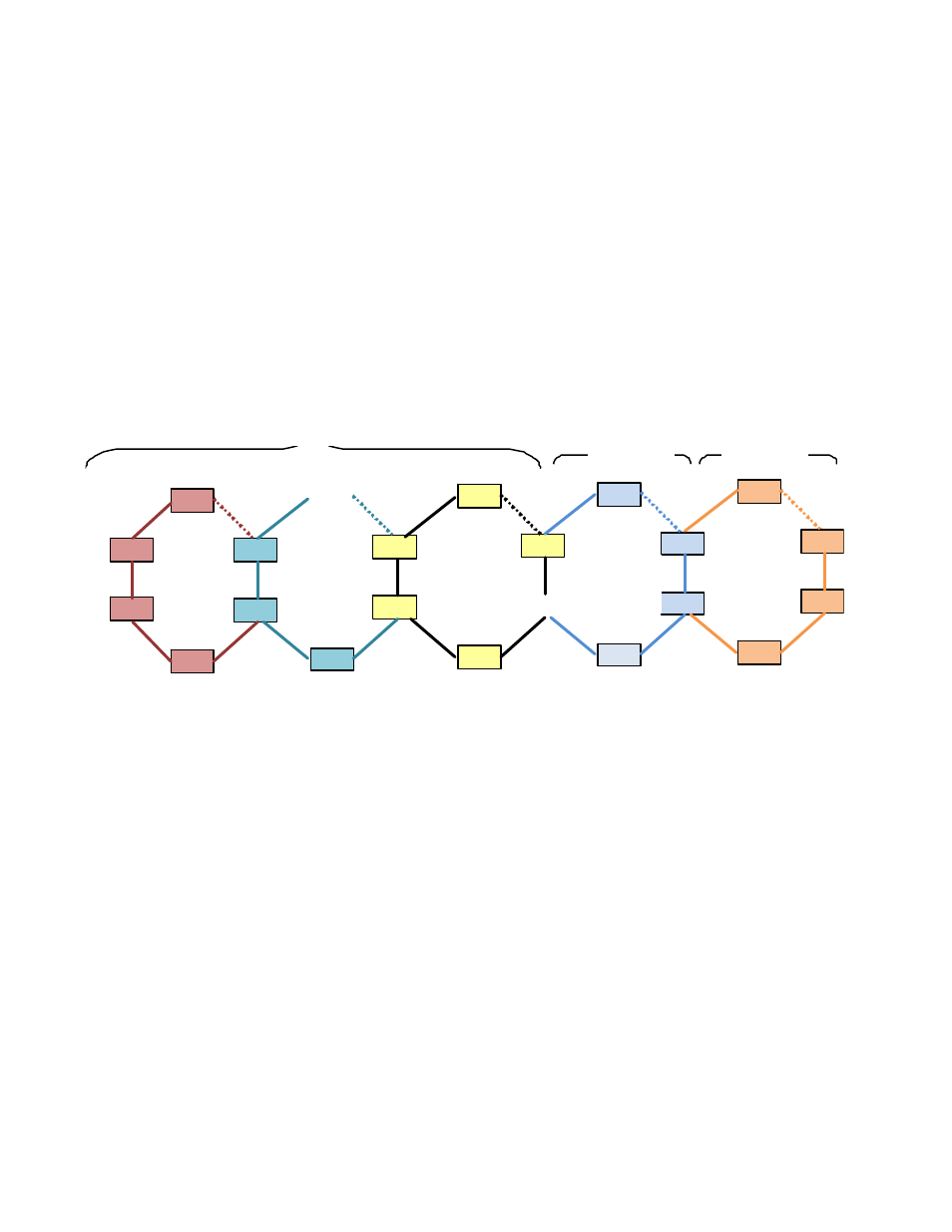
shows a diagram of one of the sample topologies that shall be
used for deploying ERP over PBB using the ESI model. In the diagram, Ring 3 is the major ring while
all others are sub-rings. Each ESI VLAN will be running a separate instance of ERP. Any ring can act
as a major ring. However, it is recommended that the B-VLAN be used as a part of Major ring.
When a network involves PB and PBB rings, one of the PBB ring must be configured as a major ring.
In the case of a PB only network, a PB ring can be the major ring. There can be only one major ring
in a given network.
FIGURE 146
ERP configuration over ESI network
In general scenarios of ERP, a multiple VLANs span across multiple rings forming a major ring and
sub-rings. The major ring and sub-ring is determined by the ERP configuration and the ERP protocol
operates keeping in focus the traffic flow.
Interconnection Rings with different VLANs
In the ESI model, traffic flow is determined by the mapping of one ESI VLAN relationship to another
ESI VLAN. In
, the ESI CVLAN1 is a client for the ESI SVLAN1 instance. So traffic from
Ring 1(CVLAN1) gets encapsulated with an S-TAG (SVLAN1) in Ring 2. Similarly, ESI SVLAN1 is a
client for the ESI BVLAN1 instance, resulting in traffic from Ring 2 encapsulated with a PBB header
in Ring 3. The traffic forwarding from Ring 3 towards Ring 4 and Ring 5 occurs as in any normal
VLAN as all the rings are running on same VLAN (BVLAN1).
To support the ERP over ESI model, each ring needs to run its own ERP instance with an ESI VLAN.
For Ring 1, the ERP instance needs to run on CVLAN1, for Ring 2 on SVLAN1 and for Rings 3, 4 and
5 on BVLAN1. Some of the nodes, such as DUT17 and DUT18, connect one ERP ring to another
ERP ring. These are called interconnection nodes. Each interconnection node in
, runs
two instances of ERP. For example, in the case of DUT17 one ERP instance is run for Ring 1 on
CVLAN1 and another ERP instance for Ring 2 on SVLAN1.
DUT 5
DU T 2
DU T 6
D UT 1
DU T 4
DUT 3
DUT 8
DUT 9
DUT 7
D UT 11
DU T 14
D UT 12
D UT 15
DU T 17
DU T 18
D UT 16
D UT 20
DU T 21
DU T 5
D UT 19
Ring 2
Sub‐Rin g
Ring 1
Sub ‐Ring
Ring 3
Ma jor Rin g
Ring 4
S b Ri
Rin g 5
S b Ri
PB VLAN
P BB VLAN
C VLAN