Figure 449, The anchor point – Grass Valley EDIUS Neo 3 User Manual
Page 398
396
EDIUS NEO — User Reference Guide
Section 5 — Timeline Operations
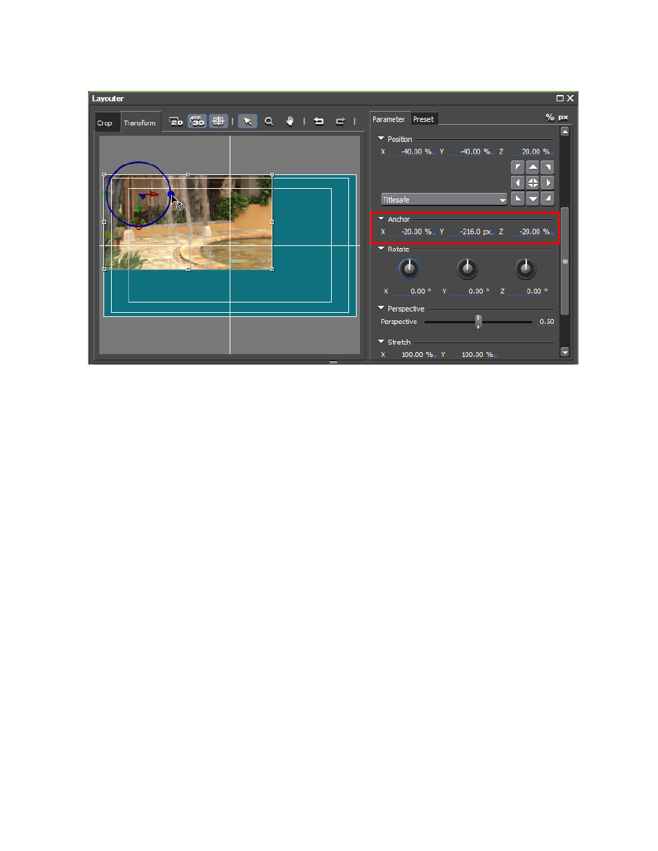
Figure 449. Layouter 3D Transform Anchor Point
Although the anchor point has shifted, the circle still circumscribes the
position location.
Note
Clicking on the blue [
] symbol next to the anchor coordinates toggles the
numeric entry for that value between percentage and a fixed number of pixels.
In
, the X and Z coordinate are in percentage and the Y coordinate
is in pixels. Clicking the % or px symbol in the upper right of the Layouter
dialog sets display and entry of all coordinate values to percentage or pixels
respectively.
3D Rotate
The source image may be rotated by entering a value (in degrees) by which
the image should be rotated around any or all of the thee axes (X, Y or Z) or
by placing the cursor over the control knob and dragging the mouse to
change the angle of the line on the knob.
Any value may be entered, but a value of -360 or 360 results in the image
being in its original position on the axis as 360 degrees is a complete rota-
tion.
Images are rotated by placing the cursor on the control point for the axis
around which you wish to rotate the image.
In the examples which follow, the image has been centered and the position
and anchor values have been reset to 0 for all three axes.
shows the rotation of the image on the X (red) axis by grabbing
the red control point and dragging the mouse cursor.