Rockwell Automation 193 Drives and Motion Accelerator Toolkit Quick Start User Manual
Page 64
64
Rockwell Automation Publication IASIMP-QS019E-EN-P - August 2013
Chapter 3
System Layout and Wiring
2.
Replace or add power components to your panel layout drawing.
a. Inspect power section on layout drawing for proper component footprints for the project.
b. Open the associated power footprint drawings that were added to your project drawings from the
toolkit library.
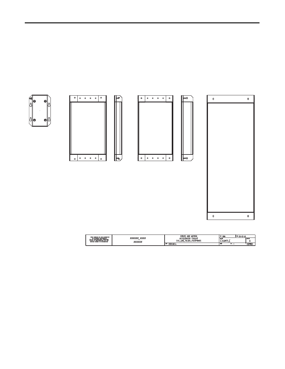
In this example, the 510_Line_Filter_Footprints.dwg file is opened.
Line Filter Footprint Drawing Examples
c. If the desired component is not represented in the current panel layout drawing, copy the proper
component footprint from the footprint drawings.
d. Delete the current component in the panel layout drawing and paste the desired component footprint
into its place.
e. Add any other required power components for your system.
FP_2090-UXLF-136
FP_2090-UXLF-HV330
FP_2090-XXLF-X330B
FP_2090-XXLF-375B_3d
- 150 Drives and Motion Accelerator Toolkit Quick Start 21G Drives and Motion Accelerator Toolkit Quick Start 20G Drives and Motion Accelerator Toolkit Quick Start 20F Drives and Motion Accelerator Toolkit Quick Start 2097 Drives and Motion Accelerator Toolkit Quick Start 2094 Drives and Motion Accelerator Toolkit Quick Start