Commissioning e3 plus overload relays, Apply power to the relay, Status indicators – Rockwell Automation 193 Drives and Motion Accelerator Toolkit Quick Start User Manual
Page 164: Devicenet commissioning
164
Rockwell Automation Publication IASIMP-QS019E-EN-P - August 2013
Chapter 6
System Commissioning
Commissioning E3 Plus Overload Relays
These commissioning procedures apply specifically to the E3 Plus overload relays when communicating with the
193-DNENCAT module.
For more information on commissioning for E3 Plus overland relays, refer to the appropriate user manual listed
in
Apply Power to the Relay
When power is applied to the DeviceNet connector, the trip relay closes if no fault exists, and the NETWORK
STATUS indicator flashes green. When the E3 Plus overload relay has been allocated by a Master, the
NETWORK STATUS indicator turns solid green. If a fault exists, the TRIP/WARN status indicator flashes.
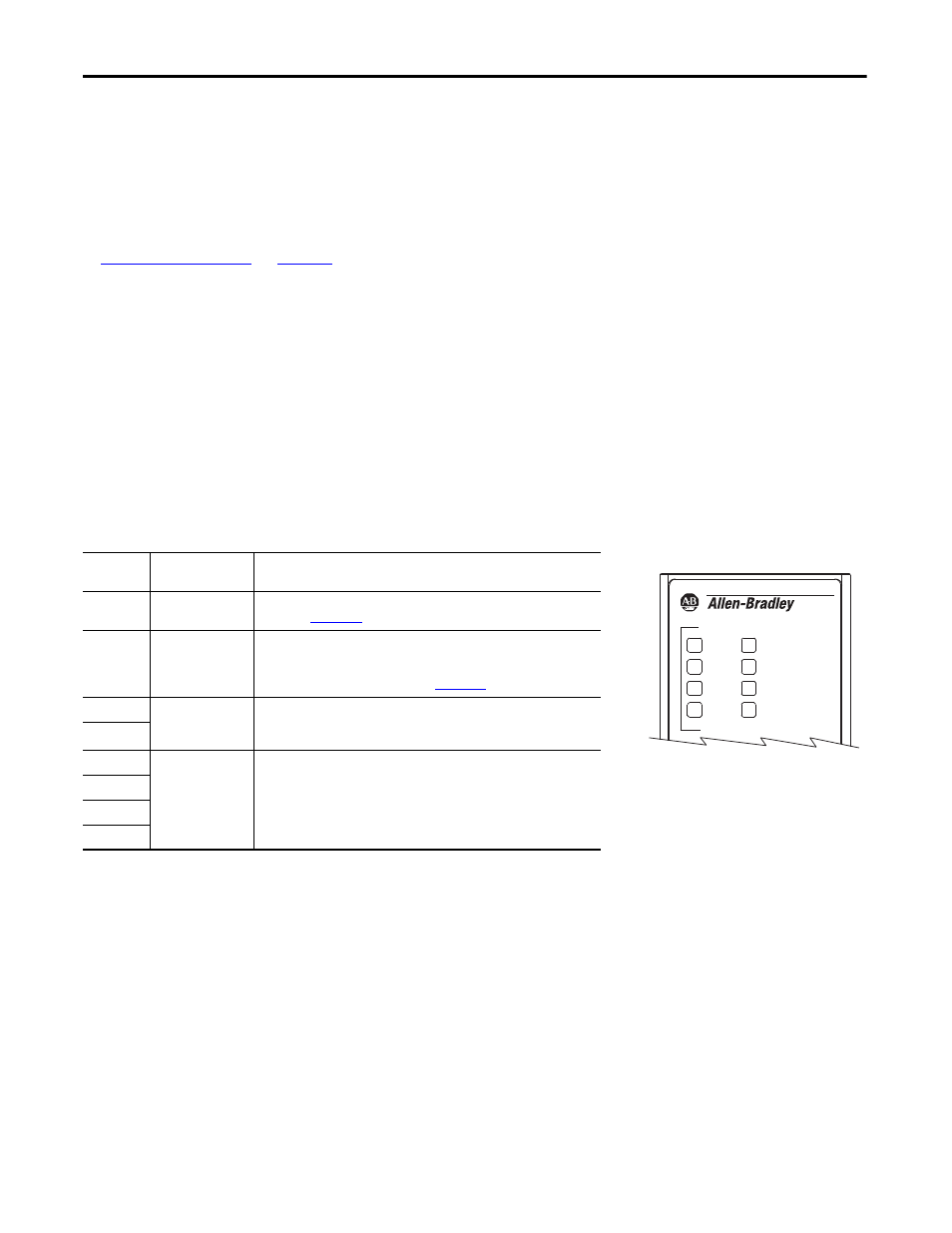
Status Indicators
The E3 Plus overload relay provides the following status indicators.
E3 Plus Status Indicators
DeviceNet Commissioning
1.
Launch RSNetWorx for DeviceNet software.
2.
Add the E3 Plus overload relay to your network configuration.
3.
Open the Motor Overload folder and double-click the desired E3 Plus overload relay.
4.
Assign the node number and desired name for the E3 Plus overload relay.
5.
Click the Parameters tab.
Status
Indicator
Function
Description
Network
Status
DeviceNet network
status
Refer to the E3 and E3 Plus Solid-state Overload Relay User Manual,
publicat
Trip/Warn
Device status
The Trip/Warn status indicator indicates device status by flashing a red trip
code or an amber warning code. The flash pattern followed by a pause
identifies the specific trip or warning. Refer to the E3 and E3 Plus Solid-state
Overload Relay User Manual, publication
.
OUT A
Output command
status
The amber OUT A or OUT B status indicator illuminates when the output is
commanded on. However, an illuminated status indicator does not guarantee
that the output is actually on.
OUT B
IN 1
Customer-supplied
contact status
The amber IN1, IN2, IN3, or IN4 status indicator illuminates when a customer-
supplied contact is closed.
IN 2
IN 3
IN 4
E3 PLUS
NETWORK
STATUS
OUT A
IN 1
IN 2
OUT B
IN 3
IN 4
TRIP
WARN
E3 Plus Status Indicators
- 150 Drives and Motion Accelerator Toolkit Quick Start 21G Drives and Motion Accelerator Toolkit Quick Start 20G Drives and Motion Accelerator Toolkit Quick Start 20F Drives and Motion Accelerator Toolkit Quick Start 2097 Drives and Motion Accelerator Toolkit Quick Start 2094 Drives and Motion Accelerator Toolkit Quick Start