Control view, Fault indication view, Control view fault indication view – Rockwell Automation 193 Drives and Motion Accelerator Toolkit Quick Start User Manual
Page 186: Powerflex drive
186
Rockwell Automation Publication IASIMP-QS019E-EN-P - August 2013
Chapter 7
System Application Guide
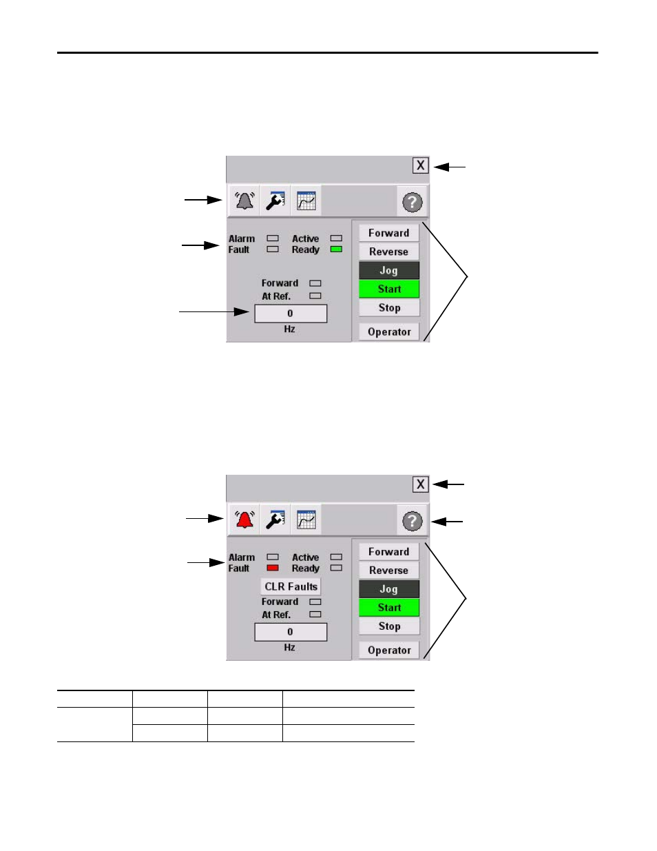
Control View
The overview faceplate places the logic program in control by default. For an operator to take control, press the
Program button. The text on the button changes to Operator and the drive command buttons (Start and Stop,
for example) are enabled.
Forward, Reverse, Jog, Start, and Stop command buttons let the operator perform the normal drive functions as
the names suggest. You can also enter a speed reference by pressing the numeric display.
Fault Indication View
The Alarm button indicates a drive fault condition and activates the fault diagnostic views.
Fault Indication View
To access the detailed fault information and action displays, press the alarm button on the toolbar.
Toolbar Button
Color Indicator
Description
Action
Alarm
(1)
(1) There is no Alarm indication on the PowerFlex 525 drive faceplate because the PowerFlex 525 drive does not support alarms.
Grey
Normal state
None
Flashing red
Fault
Follow fault action screen
Faceplate
Toolbar
Command
Buttons
Status
Indicators
Close
Button
Numeric
Display
PowerFlex Drive
Flashing Fault
Indicator
Command
Buttons
Current Fault
Indicator (red)
Close
Button
Help
Button
PowerFlex Drive
- 150 Drives and Motion Accelerator Toolkit Quick Start 21G Drives and Motion Accelerator Toolkit Quick Start 20G Drives and Motion Accelerator Toolkit Quick Start 20F Drives and Motion Accelerator Toolkit Quick Start 2097 Drives and Motion Accelerator Toolkit Quick Start 2094 Drives and Motion Accelerator Toolkit Quick Start