Select power and control, Component layout footprint, Drawings – Rockwell Automation 193 Drives and Motion Accelerator Toolkit Quick Start User Manual
Page 267
Rockwell Automation Publication IASIMP-QS019E-EN-P - August 2013
267
Assemble Project Drawing Set Without the DMAT Wizard
Appendix F
7.
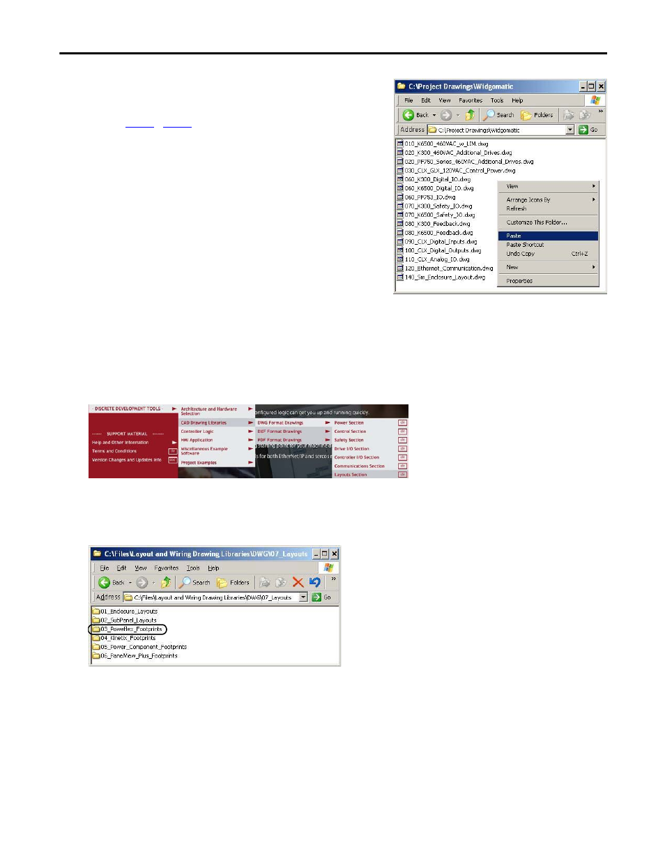
Paste the subpanel drawing into your Project Drawings
folder.
8.
for every unique enclosure you have in
your system.
Select Power and Control Component Layout Footprint Drawings
1.
Navigate to the desired (DWG, DXF, or PDF) file type folder on the toolkit DVD and select Layouts
Section.
2.
Double-click the 03_Poweflex_Footprints, 04_Kinetix_Footprints, 05_Power_Component_Footprints,
or 06_PanelView_Plus_Footprints folder to access the corresponding power or control component
footprints within your system for later insertion into your subpanel or communication drawings.
For the Widg-O-matic machine application example, the 03_Poweflex_Footprints folder was initially
selected.
- 150 Drives and Motion Accelerator Toolkit Quick Start 21G Drives and Motion Accelerator Toolkit Quick Start 20G Drives and Motion Accelerator Toolkit Quick Start 20F Drives and Motion Accelerator Toolkit Quick Start 2097 Drives and Motion Accelerator Toolkit Quick Start 2094 Drives and Motion Accelerator Toolkit Quick Start