Control circuit wiring, Control circuit connection diagram, Control circuit terminal block functions – Yaskawa AC Drive-P1000 Industrial Fan User Manual
Page 94: 9 control circuit wiring, Refer to control
3.9 Control Circuit Wiring
u
Control Circuit Connection Diagram
on page
when wiring terminals on the drive control circuit.
u
Control Circuit Terminal Block Functions
Drive parameters determine which functions apply to the multi-function digital inputs (S1 to S8), multi-function digital outputs
(M1 to M4), multi-function analog inputs (A1 to A3), and multi-function analog monitor output (FM, AM). The default setting
is listed next to each terminal in
.
WARNING!
Sudden Movement Hazard. Always check the operation and wiring of control circuits after being wired. Operating a drive with
untested control circuits could result in death or serious injury.
WARNING!
Sudden Movement Hazard. Confirm the drive I/O signals and external sequence before starting test run. Setting parameter
A1-03 may change the I/O terminal function automatically from the factory setting.
Refer to Application Selection on page 126
comply may result in death or serious injury.
n
Input Terminals
lists the input terminals on the drive. Text in parenthesis indicates the default setting for each multi-function input.
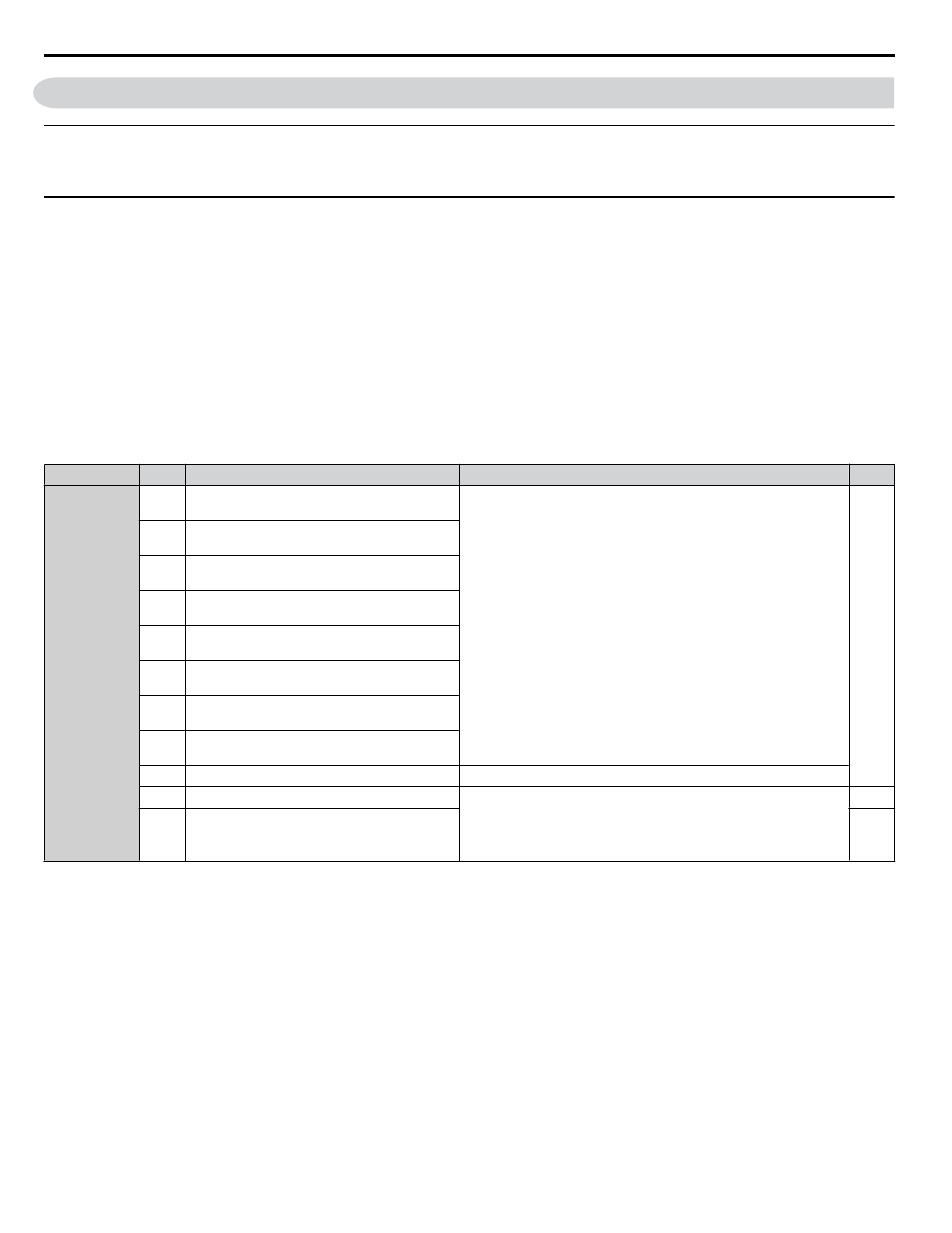
Table 3.7 Control Circuit Input Terminals
Type
No.
Terminal Name (Function)
Function (Signal Level) Default Setting
Page
Multi-Function
Digital Inputs
S1
Multi-function input 1
(Closed: Forward run, Open: Stop)
• Photocoupler
• 24 Vdc, 8 mA
•
Refer to Sinking/Sourcing Mode for Digital Inputs on page
S2
Multi-function input 2
(Closed: Reverse run, Open: Stop)
S3
Multi-function input 3
(External fault, N.O.)
S4
Multi-function input 4
(Fault reset)
S5
Multi-function input 5
(Multi-step speed reference 1)
S6
Multi-function input 6
(Multi-step speed reference 2)
S7
Multi-function input 7
(Jog reference)
S8
Multi-function input 8
(Baseblock command (N.O.))
SC
Multi-function input common
Multi-function input common
SP
Digital input power supply +24 Vdc
24 Vdc power supply for digital inputs, 150 mA max
NOTICE:
Do not jumper or short terminals SP and SN. Failure
to comply will damage the drive.
SN
Digital input power supply 0 V
24 V transducer power supply 0 V
3.9 Control Circuit Wiring
94
YASKAWA SIEP YAIP1U 01B AC Drive - P1000 Technical Manual