Figure 8.16, For proper configuration, Using braking units in parallel – Yaskawa AC Drive-P1000 Industrial Fan User Manual
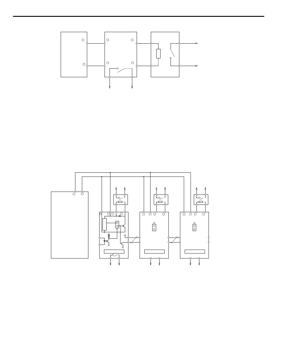
Page 386: 5 installing peripheral devices, Figure 8.17 connecting braking units in parallel
Thermal Relay
Trip Contact
Drive
Braking Unit
(CDBR type)
Braking Resistor Unit
(LKEB type)
Thermal Overload
Protector Trip Contact
1
2
P
3
4
3
+
+ 0
−
− 0
B
+
−
Figure 8.16 Connecting a Braking Unit (CDBR type) and Braking Resistor Unit (LKEB type)
Models 2A0169 to 2A0415, 4A0088 to 4A1200 and 5A0125 to 5A0242
Note:
To install a CDBR type braking unit to the drive with a built-in dynamic braking transistor (models 2A0004 to 2A0138,
4A0002 to 4A0072, and 5A0003 to 5A0052), connect the drive B1 terminal to the positive terminal on the braking unit. Next, wire the
negative terminals on the drive and braking unit together. Terminal B2 is not used.
n
Using Braking Units in Parallel
When using multiple braking units, install the braking units with a master-slave configuration with a single braking unit acting
illustrates how to wire braking units in parallel.
Wire the normally open thermal overload contact relays of all CDBRs and all braking resistors in parallel, then connect this
signal to a control circuit as shown in
to interrupt the main input power supply to the drive in the event of a CDBR
or braking resistor overload.
Drive
Braking Resistor
Overheat Contact
(Thermal Relay Trip Contact)
Braking Resistor
Overheat Contact
(Thermal Relay Trip Contact)
Braking Resistor
Overheat Contact
(Thermal Relay Trip Contact)
Braking
Resistor
Unit
Braking
Resistor
Unit
Braking
Resistor
Unit
Braking Unit 2
+15
5
1
2
6
SLAVE
MASTER
Level Detector
Cooling Fin Overheat Contact
(Thermoswitch Contact)
Cooling Fin Overheat Contact
(Thermoswitch Contact)
Cooling Fin Overheat Contact
(Thermoswitch Contact)
Braking Unit 3
Braking Unit 1
1
3
4
3
4
3
5
6
5
6
1
2
4
2
3
1
P
2
B
−
− 0
+ 0
+
−
+
−
+
−
+ 0
− 0
+ 0
− 0
B
P
B
P
1
2
1
2
MASTER
SLAVE
MASTER
SLAVE
+
Figure 8.17 Connecting Braking Units in Parallel
8.5 Installing Peripheral Devices
386
YASKAWA SIEP YAIP1U 01B AC Drive - P1000 Technical Manual