Yaskawa AC Drive-P1000 Industrial Fan User Manual
Page 316
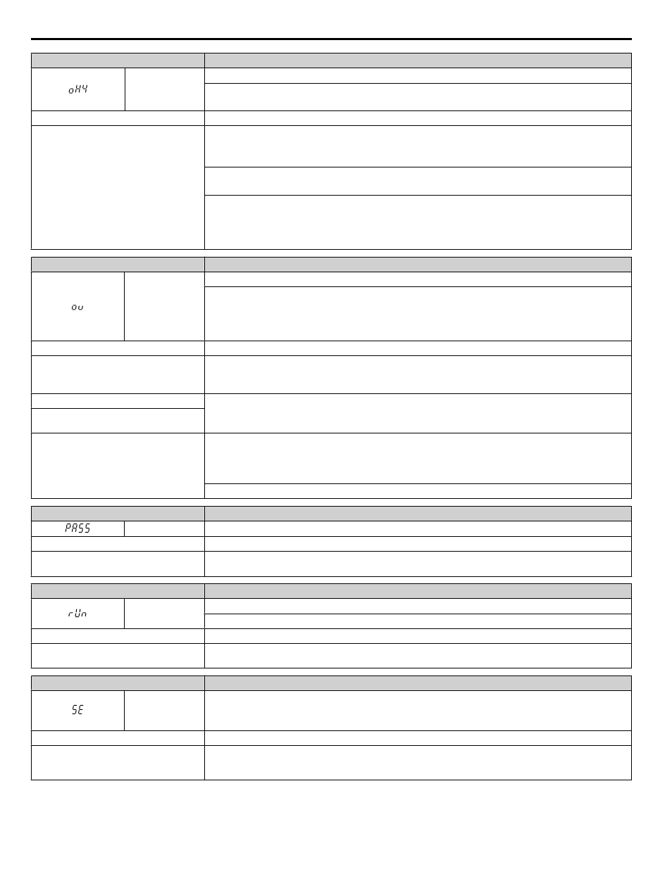
Digital Operator Display
Fault Name
oH4
Motor Overheat Fault (PTC Input)
• The motor overheat signal to analog input terminal A1, A2, or A3 exceeded the fault detection level.
• Detection requires setting multi-function analog inputs H3-02, H3-10, or H3-06 to E.
Cause
Possible Solution
Motor has overheated
• Check the size of the load, the accel/decel times, and the cycle times.
• Decrease the load.
• Increase the acceleration and deceleration times (C1-01 through C1-04).
• Adjust the preset V/f pattern (E1-04 through E1-10) by reducing E1-08 and E1-10.
• Do not set E1-08 and E1-10 too low. This reduces load tolerance at low speeds.
• Check the motor rated current.
• Enter the motor rated current to parameter E2-01 as indicated on the motor nameplate.
• Ensure the motor cooling system is operating normally.
• Repair or replace the motor cooling system.
Digital Operator Display
Minor Fault Name
ov
DC Bus Overvoltage
The DC bus voltage exceeded the trip point.
• For 200 V class drives: approximately 410 V
• For 400 V class drives: approximately 820 V (740 V when E1-01 is less than 400)
• For 600 V class drives: approximately 1040 V
Cause
Possible Solutions
Surge voltage present in the drive input
power.
• Install a DC link choke or an AC reactor.
• Voltage surge can result from a thyristor convertor and a phase advancing capacitor operating on the same
drive input power system.
The motor is short-circuited.
• Check the motor power cable, relay terminals and motor terminal box for short circuits.
• Correct grounding shorts and turn the power back on.
Ground current has overcharged the main
circuit capacitors via the drive input power.
Noise interference causes the drive to
operate incorrectly.
• Review possible solutions for handling noise interference.
• Review section on handling noise interference and check control circuit lines, main circuit lines and ground
wiring.
• If the magnetic contactor is identified as a source of noise, install a surge protector to the MC coil.
Set number of fault restarts (L5-01) to a value other than 0.
Digital Operator Display
Minor Fault Name
PASS
MEMOBUS/Modbus Comm. Test Mode Complete
Cause
Possible Solutions
MEMOBUS/Modbus test has finished
normally.
This verifies that the test was successful.
Digital Operator Display
Minor Fault Name
rUn
Motor Switch during Run
A command to switch motors was entered during run.
Cause
Possible Solutions
A motor switch command was entered
during run.
Change the operation pattern so that the motor switch command is entered while the drive is stopped.
Digital Operator Display
Minor Fault Name
SE
MEMOBUS/Modbus Communication Test Mode Error
Note:
This alarm will not trigger a multi-function output terminal that is set for alarm output
(H2-oo = 10).
Cause
Possible Solutions
A digital input set to 67H (MEMOBUS/
Modbus test) was closed while the drive
was running.
Stop the drive and run the test again.
6.5 Alarm Detection
316
YASKAWA SIEP YAIP1U 01B AC Drive - P1000 Technical Manual