Yaskawa AC Drive-P1000 Industrial Fan User Manual
Page 331
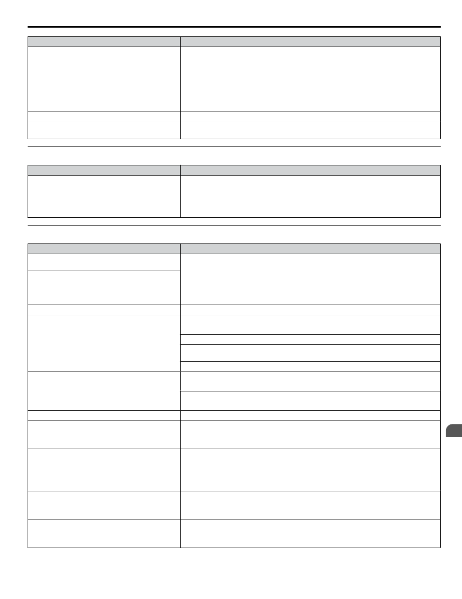
Cause
Possible Solutions
Insufficient voltage insulation between motor phases.
When the motor cable is long, high voltage surges occur between the motor coils and drive
switching.
Normally, surges can reach up to three times the drive input power supply voltage.
• Use a motor with a voltage tolerance higher than the max voltage surge.
• Use an inverter-duty motor rated for use with AC drives when using the motor on drives rated
higher than 200 V class.
• Install an AC reactor on the output side of the drive. The carrier frequency should be set to 2
kHz when installing an AC reactor.
The motor fan has stopped or is clogged.
Check the motor fan.
The carrier frequency is too low.
Increase the carrier frequency to lower the current harmonic distortion and lower the motor
temperature.
u
oPE02 Error Occurs When Lowering the Motor Rated Current Setting
Cause
Possible Solutions
Motor rated current and the motor no-load current
setting in the drive are incorrect.
• The user is trying to set the motor rated current in E2-01 to a value lower than the no-load
current set in E2-03.
• Make sure that value set in E2-01 is higher than E2-03.
• If it is necessary to set E2-01 lower than E2-03, first lower the value set to E2-03, then change
the setting in E2-01 as needed.
u
Motor Stalls during Acceleration or Acceleration Time is Too Long
Cause
Possible Solutions
Torque limit has been reached or current suppression
keeps the drive from accelerating.
Take the following steps to resolve the problem:
• Reduce the load.
• Increase motor capacity.
Note:
Although the drive has a Stall Prevention function and a Torque Compensation
Limit function, accelerating too quickly or trying to drive an excessively large
load can exceed the capabilities of the motor.
Load is too heavy.
Torque limit is not set properly.
Check the torque limit setting.
Frequency reference is too low.
• Check the maximum output frequency (E1-04).
• Increase E1-04 if it is set too low.
Check U1-01 for proper frequency reference.
Check if a frequency reference signal switch has been set to one of the multi-function input
terminals.
Check for low gain level set to terminals A1, A2, or A3 (H3-03, H3-11, H3-07).
Load is too heavy.
• Reduce the load so that the output current remains within the motor rated current.
• In extruder and mixer applications, the load will sometimes increase as the temperature drops.
• Increase the acceleration time.
• Check if the mechanical brake is fully releasing as it should.
Acceleration time has been set too long.
Check if the acceleration time parameters have been set too long (C1-01, C1-03).
Motor characteristics and drive parameter settings are
incompatible with one another.
• Set the correct V/f pattern so that it matches the characteristics of the motor being used.
• Check the V/f pattern set to E1-03.
• Execute Rotational Auto-Tuning.
Incorrect frequency reference setting.
• Check the multi-function analog input settings. Multi-function analog input terminal A1, A2,
or A3 is set for frequency gain (H3-02, H3-10, or H3-06 is set to “1”), but there is no voltage
or current input provided.
• Make sure H3-02, H3-10, and H3-06 are set to the proper values.
• See if the analog input value is set to the right value (U1-13 to U1-15).
The Stall Prevention level during acceleration and
deceleration set too low.
• Check the Stall Prevention level during acceleration (L3-02).
• If L3-02 is set too low, acceleration may be taking too long.
• Increase L3-02.
The Stall Prevention level during run has been set too
low.
• Check the Stall Prevention level during run (L3-06).
• If L3-06 is set too low, speed will drop as the drive outputs torque.
• Increase the setting value.
6.10 Troubleshooting without Fault Display
YASKAWA SIEP YAIP1U 01B AC Drive - P1000 Technical Manual
331
6
Troubleshooting