Yaskawa AC Drive-P1000 Industrial Fan User Manual
Page 248
n
L3-04: Stall Prevention Selection during Deceleration
Stall Prevention during deceleration controls the deceleration based on the DC bus voltage and prevents an overvoltage fault
caused by high inertia or rapid deceleration.
No.
Name
Setting Range
Default
L3-04
Stall Prevention Selection During Deceleration
0 to 5
<1>
1
<1> Setting 3 is not available in models 4A0930 or 4A1200.
Setting 0: Disabled
The drive decelerates according to the set deceleration time. With high inertia loads or rapid deceleration, an overvoltage fault
may occur. If an overvoltage fault occurs, use dynamic braking options or switch to another L3-04 selection.
Setting 1: General-purpose Stall Prevention
The drive tries to decelerate within the set deceleration time. The drive pauses deceleration when the DC bus voltage exceeds
the Stall Prevention level and then continues deceleration when the DC bus voltage drops below that level. Stall Prevention
may be triggered repeatedly to avoid an overvoltage fault. The DC bus voltage level for Stall Prevention depends on the input
voltage setting E1-01.
Drive Input Voltage
Stall Prevention Level during Deceleration
200 V Class
377 Vdc
400 V Class
754 Vdc
600 V Class
1084 Vdc
Note:
1. Do not use this setting in combination with a Dynamic Braking Resistor or other dynamic braking options. If Stall Prevention during
deceleration is enabled, it will be triggered before the braking resistor option can operate.
2. This method may lengthen the total deceleration time compared to the set value. If this is not appropriate for the application consider
using a dynamic braking option.
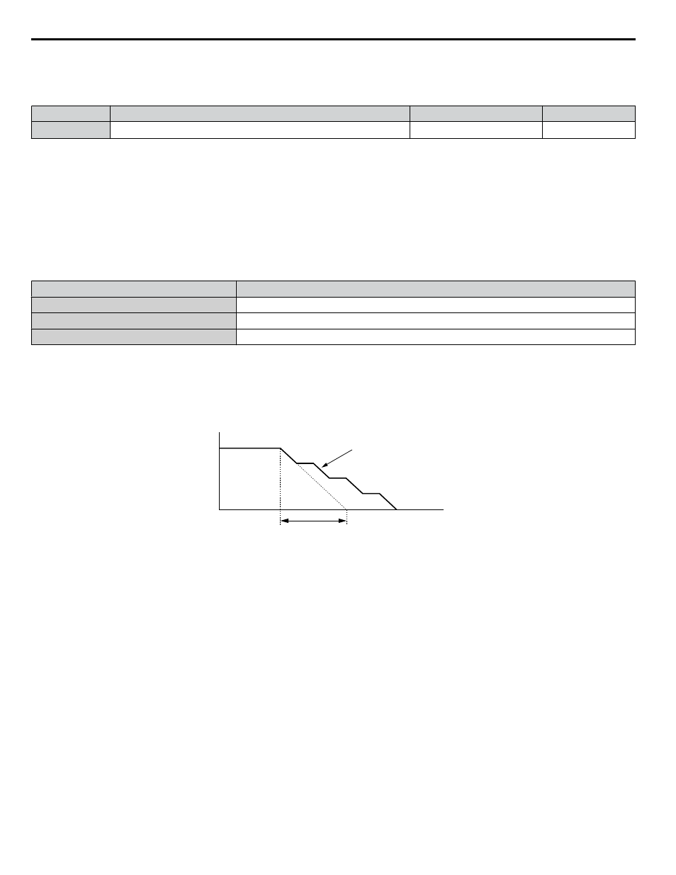
illustrates the function of Stall Prevention during deceleration.
Output Frequency
Deceleration characteristics
when Stall Prevention was
triggered during deceleration
Time
specified deceleration time
Figure 5.79 Stall Prevention During Deceleration
Setting 2: Intelligent Stall Prevention
The drive adjusts the deceleration rate so the DC bus voltage is kept at the level set to parameter L3-17. This produces the
shortest possible deceleration time while protecting the motor from stalling. The selected deceleration time is disregarded and
the achievable deceleration time cannot be smaller than 1/10 of the set deceleration time.
This function uses the following parameters for adjusting the deceleration rate:
• DC bus voltage gain (L3-20)
• Deceleration rate calculations gain (L3-21)
• Inertia calculations for motor acceleration time (L3-24)
• Load inertia ratio (L3-25)
Note:
The deceleration time is not constant. Do not use Intelligent Stall Prevention in applications where stopping accuracy is a concern. Use
dynamic braking options instead.
Setting 3: Stall Prevention with dynamic braking option
Enables the Stall Prevention function while using a dynamic braking resistor.
Setting 4: Overexcitation Deceleration 1
Overexcitation Deceleration 1 (increasing the motor flux) is faster than deceleration with no Stall Prevention (L3-04 = 0).
Setting 4 changes the selected decel time and functions to provide protection from an overvoltage trip.
Deceleration (Induction Motors) on page 264
5.8 L: Protection Functions
248
YASKAWA SIEP YAIP1U 01B AC Drive - P1000 Technical Manual