D.3 ul and csa standards – Yaskawa AC Drive-P1000 Industrial Fan User Manual
Page 539
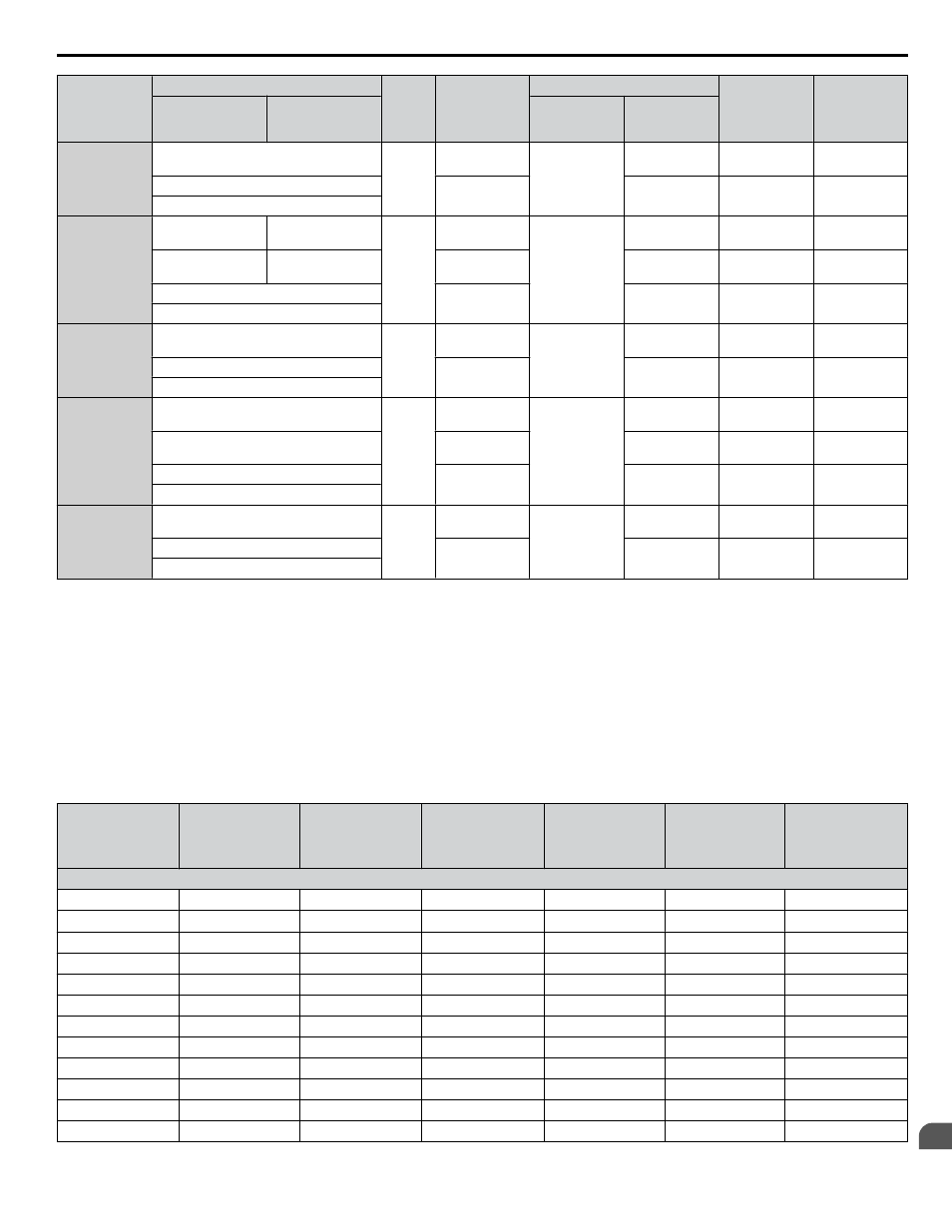
Drive Model
Wire Gauge (AWG, kcmil)
Screw
Size
Crimp
Terminal
Model Number
Tool
Insulation Cap
Model No.
Code
<1>
R/L1, S/L2, T/L3 U/T1, V/T2, W/T3
Machine No.
Die Jaw
4A0414
4/0 × 2P
M12
100-L12
YF-1
YET-300-1
TD-324,
TD-312
TP-100
100-051-560
250 × 2P
150-L12
TD-325,
TD-313
TP-150
100-051-562
300 × 2P
4A0515
3/0 × 4P
3/0 × 4P
M12
80-L12
YF-1
YET-300-1
TD-323,
TD-312
TP-080
100-051-558
4/0 × 4P
4/0 × 4P
100-L12
TD-324,
TD-312
TP-100
100-051-560
250 × 4P
150-L12
TD-325,
TD-313
TP-150
100-051-562
300 × 2P
4A0675
4/0 × 4P
M12
100-L12
YF-1
YET-300-1
TD-324,
TD-312
TP-100
100-051-560
250 × 4P
150-L12
TD-325,
TD-313
TP-150
100-051-562
300 × 4P
4A0930
3/0 × 8P
M12
80-L12
YF-1
YET-300-1
TD-323,
TD-312
TP-080
100-051-558
4/0 × 8P
100-L12
TD-324,
TD-312
TP-100
100-051-560
250 × 8P
150-L12
TD-325,
TD-313
TP-150
100-051-562
300 × 8P
4A1200
4/0 × 8P
M12
100-L12
YF-1
YET-300-1
TD-324,
TD-312
TP-100
100-051-560
250 × 8P
150-L12
TD-325,
TD-313
TP-150
100-051-562
300 × 8P
<1> Codes refer to a set of three crimp terminals and three insulation caps. Prepare input and output wiring using two sets for each connection.
Example 1: Models with 300 kcmil for both input and output require one set for input terminals and one set for output terminals, so the user should
order two sets of [100-051-272].
Example 2: Models with 4/0 AWG × 2P for both input and output require two sets for input terminals and two sets for output terminals, so the user
should order four sets of [100-051-560].
Note:
Use crimp insulated terminals or insulated shrink tubing for wiring connections. Wires should have a continuous maximum allowable
temperature of 75 °C 600 Vac UL-approved vinyl-sheathed insulation.
Input Fuse Installation
Yaskawa recommends installing one of the following types of branch circuit protection to maintain compliance with UL508C.
Table D.8 Factory Recommended AC Drive Branch Circuit Protection (Normal Duty)
Drive Model
Nominal
Output Power
HP
AC Drive Input
Amps
MCCB Rating
Amps
<1>
Time Delay Fuse
Rating Amps
<2>
Non-time Delay
Fuse Rating Amps
<3>
Bussman Semi-
conductor Fuse
Rating (Fuse
Ampere)
<4>
200 V Class
2A0004
0.75
3.9
15
6.25
10
FWH-70B (70)
2A0006
1 - 1.5
7.3
15
12
20
FWH-70B (70)
2A0008
2
8.8
15
15
25
FWH-70B (70)
2A0010
3
10.8
20
17.5
30
FWH-70B (70)
2A0012
3
13.9
25
20
40
FWH-70B (70)
2A0018
5
18.5
35
30
50
FWH-90B (90)
2A0021
7.5
24
45
40
70
FWH-90B (90)
2A0030
10
37
60
60
110
FWH-100B (100)
2A0040
15
52
100
90
150
FWH-200B (200)
2A0056
20
68
125
110
200
FWH-200B (200)
2A0069
25
80
150
125
225
FWH-200B (200)
2A0081
30
96
175
150
275
FWH-300A (300)
D.3 UL and CSA Standards
YASKAWA SIEP YAIP1U 01B AC Drive - P1000 Technical Manual
539
D
Standards Compliance