Terminal block configuration, 4 terminal block configuration – Yaskawa AC Drive-P1000 Industrial Fan User Manual
Page 75
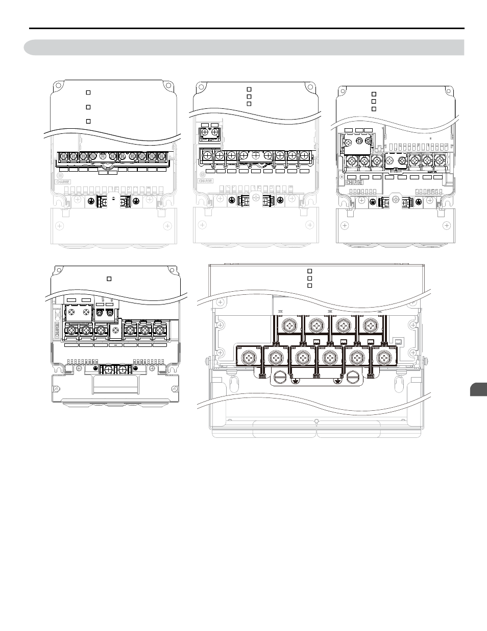
3.4 Terminal Block Configuration
show the different main circuit terminal arrangements for the drive capacities.
R/L1 S/L2 T/L3 _
+1
+2
B1
B2
U/T1
V/T2 W/T3
R/L1 S/L2 T/L3
_
+1
+2
U/T1
V/T2
W/T3
B1
B2
R/L1
S/L2
T/L3
U/T1
V/T2 W/T3
+1
+2
B1
B2
–
CIMR-P 2A0004, 0006, 0008, 0010,
0012, 0018, 0021
CIMR-P 4A0002, 0004, 0005, 0007
0009, 0011
CIMR-P 5A0003, 0004, 0006, 0009
CIMR-P 2A0030, 0040
CIMR-P 4A0018, 0023
CIMR-P 5A0011
CIMR-P 2A0056
CIMR-P 4A0031, 0038, 0044
CIMR-P 5A0017, 0022, 0027, 0032
B1
B2
+1
+2
R/L1
S/L2
T/L3
U/T1
V/T2
W/T3
CIMR-P 2A0110, 0138
CIMR-P 4A0058, 0072
CIMR-P 2A0069, 0081
B1
B2
_
+1
R/L1
S/L2
T/L3
U/T1
V/T2 W/T3
CIMR-P 5A0041, 0052
Figure 3.9 Main Circuit Terminal Block Configuration
3.4 Terminal Block Configuration
YASKAWA SIEP YAIP1U 01B AC Drive - P1000 Technical Manual
75
3
Electrical Installation