B4: delay timers, B5: pid control – Yaskawa AC Drive-P1000 Industrial Fan User Manual
Page 159
n
b3-27: Start Speed Search Select
Selects a condition to activate Speed Search Selection at Start (b3-01) or External Speed Search Command 1 or 2 from the
multi-function input.
No.
Name
Setting Range
Default
b3-27
Start Speed Search Select
0, 1
0
Setting 0: Triggered when a Run Command Is Issued (Normal)
Setting 1: Triggered when an External Baseblock Is Released
u
b4: Delay Timers
The timer function is independent of drive operation and can delay the switching of a digital output triggered by a digital input
signal and help eliminate chattering switch noise from sensors. An on-delay and off-delay can be set separately.
To enable the timer function, set a multi-function input to “Timer input” (H1-oo = 18) and set a multi-function output to
“Timer output” (H2-oo = 12). Only one timer can be used.
n
b4-01, b4-02: Timer Function On-Delay, Off-Delay Time
b4-01 sets the on-delay time for switching the timer output. b4-02 sets the off-delay time for switching the timer output.
No.
Name
Setting Range
Default
b4-01
Timer Function On-Delay Time
0.0 to 3000.0 s
0.0 s
b4-02
Timer Function Off-Delay Time
0.0 to 3000.0 s
0.0 s
n
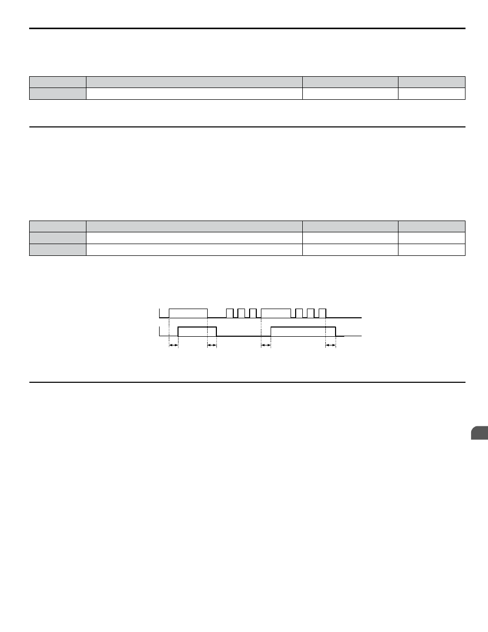
Timer Function Operation
The timer function switches on when the timer function input closes for longer than the value set to b4-01. The timer function
switches off when the timer function input is open for longer than the value set to b4-02.
function operation:
b4-01
b4-02
b4-01
b4-02
Multi-function Contact
Input: Timer Function
On (Closed)
Off (Open)
On (Closed)
Off (Open)
Multi-function Contact
Output: Timer Function
ON
ON
ON
ON
Figure 5.13 Timer Operation
u
b5: PID Control
The drive has a built-in Proportional + Integral + Derivative (PID) controller that uses the difference between the target value
and the feedback value to adjust the drive output frequency to minimize deviation and provide accurate closed loop control
of system variables such as pressure or temperature.
n
P Control
The output of P control is the product of the deviation and the P gain so that it follows the deviation directly and linearly. With
P control, only an offset between the target and feedback remains.
n
I Control
The output of I control is the integral of the deviation. It minimizes the offset between target and feedback value that typically
remains when pure P control is used. The integral time (I time) constant determines how fast the offset is eliminated.
n
D Control
D control predicts the deviation signal by multiplying its derivative (slope of the deviation) with a time constant, then adds
this value to the PID input. This way the D portion of a PID controller provides a braking action to the controller response and
can reduce the tendency to oscillate and overshoot.
D control tends to amplify noise on the deviation signal, which can result in control instability. Only use D control when
absolutely necessary.
5.2 b: Application
YASKAWA SIEP YAIP1U 01B AC Drive - P1000 Technical Manual
159
5
Parameter Details