S3: secondary pi (pi2) control, S3-01: secondary pi enable selection, S3-02: secondary pi user display – Yaskawa AC Drive-P1000 Industrial Fan User Manual
Page 280
No.
Name
Setting Range
Default
S2-05
Sequence Timer 1 Reference Source
0 to 7
0
S2-10
Sequence Timer 2 Reference Source
0 to 7
0
S2-15
Sequence Timer 3 Reference Source
0 to 7
0
S2-20
Sequence Timer 4 Reference Source
0 to 7
0
Setting 0: Operator (d1-01)
Setting 1: Operator (d1-02)
Setting 2: Operator (d1-03)
Setting 3: Operator (d1-04)
Setting 4: Terminals
Setting 5: Serial Communication
Setting 6: Option Card
Setting 7: Pulse Input
u
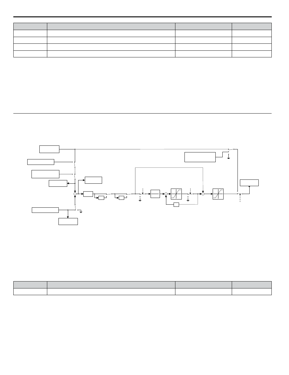
S3: Secondary PI (PI2) Control
The drive has a built in PI (Proportional + Integral) controller that can be used for closed loop control of system variables such
as pressure or temperature. The difference between the target and the feedback value (deviation) is fed into the PI controller
and the PI controller outputs the frequency to U5-oo for monitoring.
Refer to b5: PID Control on page 159
for details.
S3-06
PI2 P Gain
-1
PI2 I Time
1
S3-07
+
+
S3-08
PI2 I Limit
<1>
z
-1
PI2 Invert
Multi-function
Input Closed
+
+
Upper Limit:
S3-09
PI2 Output Upper
Limit
Lower Limit:
S3-10
PI2 Output Lower Limit
U5-19
PI2 Input
-1
S3-11 = 0
S3-11 = 1
PI2
Integral
Hold Multi-
function
Input
PI2 Integral
Reset Multi-
Function Input
MEMOBUS XXXXh
PI2 Setpoint
MEMOBUS
000FH
bit 4 = 1
S3-05
PI Setpoint
+
Terminal A1/A2/A3
-
U5-17
PI2 Setpoint
U5-18
PI2 Feedback
U5-20
PI2 Output
Lower Limit:
S3-10
PI2 Output Lower Limit
PI2 Disable
Multi-function
Input
<2>
S3-12
0
1
2
<1> Actual integral limit is calculated as follows:
Upper limit = Min (S3-08, S3-09 - PI2 P portion)
Lower limit = Min (-S3-08, S3-10 - PI2 P portion)
<2> When PI2 Disable multi-function input is closed, set PI Integrator as follows:
S3-12 = 1: PI I Value = S3-10
S3-12 = 2: PI I Value = S3-05
H3-02/
H3-06/
H3-10=26
Terminal A1/A2/A3
H3-02/H3-06/
H3-10=26
Figure 5.94 PI2 Block Diagram
n
S3-01: Secondary PI Enable Selection
Determines when the secondary PI controller is enabled.
No.
Name
Setting Range
Default
S3-01
Secondary PI Enable Selection
0 to 3
0
Setting 0: Secondary PI Disabled
Setting 1: Always
Setting 2: Drive Running
Setting 3: Motor Running
Available when the drive is not at zero speed, not in base block, and not in DC injection.
n
S3-02: Secondary PI User Display
Sets the scale value of 100% PI input. The decimal place shifts based on S3-03.
5.11 S: Special Application
280
YASKAWA SIEP YAIP1U 01B AC Drive - P1000 Technical Manual