Communication option installation example – Yaskawa AC Drive-P1000 Industrial Fan User Manual
Page 381
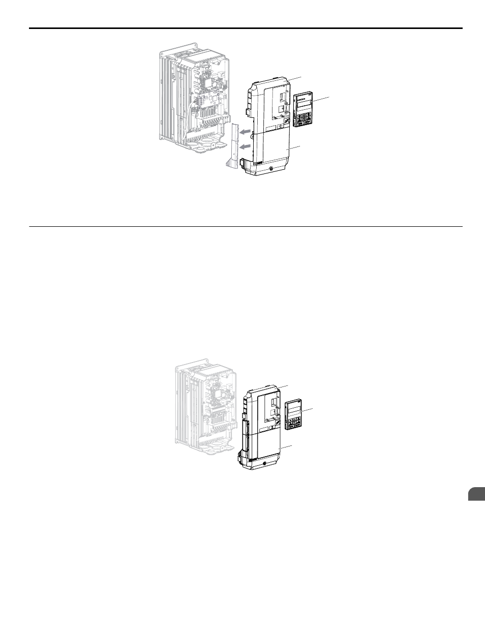
D
A
B
NS MS
TX RX
Figure 8.7 Replace the Front Covers and Digital Operator
Note:
Take proper precautions when wiring the option so that the front covers will easily fit back onto the drive. Make sure no cables
are pinched between the front covers and the drive when replacing the covers.
u
Communication Option Installation Example
Remove the front covers of the drive before installing the option. Communication options can inserted only into the CN5-A
connector located on the drive control board.
Preparing the Drive
1.
Shut off power to the drive, wait the appropriate amount of time for voltage to dissipate, then remove the digital operator
(B) and front covers (A, D). Front cover removal varies by model.
DANGER!
Electrical Shock Hazard. Do not connect or disconnect wiring while the power is on. Failure to comply will result in death
or serious injury. Before installing the option, disconnect all power to the drive. The internal capacitor remains charged even after
the power supply is turned off. The charge indicator LED will extinguish when the DC bus voltage is below 50 Vdc. To prevent
electric shock, wait at least five minutes after all indicators are off and measure the DC bus voltage level to confirm safe level.
NOTICE:
Damage to Equipment. Observe proper electrostatic discharge procedures (ESD) when handling the option, drive, and
circuit boards. Failure to comply may result in ESD damage to circuitry.
A
B
D
Figure 8.8 Remove the Front Covers and Digital Operator
2.
With the front covers and digital operator removed, apply the LED label (C) in the appropriate position on the drive
top front cover (A).
8.4 Option Installation
YASKAWA SIEP YAIP1U 01B AC Drive - P1000 Technical Manual
381
8
Peripheral Devices & Options