Yaskawa MP920 User's Manual Design User Manual
Page 96
3 Basic System Operation
3.4.3 Motion Programming
3-22
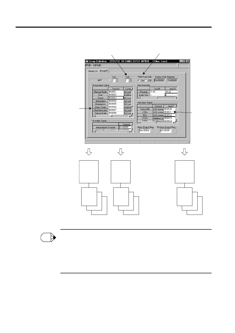
• The ladder logic programs that are generated for motion program control are created automatically
using the external input signals that are allocated on the Group Definition Window. These ladder
logic programs can also be used as is. It is recommended, however, that they be used as templates
to be optimized (changed) to suit individual system requirement.
• When a ladder logic programs used for motion program control is created by automatic generation,
up to eight motion programs can be called simultaneously from the ladder logic program. In other
words, when automatic generation is used, a maximum of eight groups will be controlled.
H01
H02
H08
Group 1
Group 2
Group 8
H01.03
H01.02
H01.01
H01.03
H01.02
H02.01
H01.03
H01.02
H08.01
Main motion
management
ladder logic
program for
Group 1
.
.
.
.
.
.
.
.
.
Manual
management
ladder logic
program for
axis 1
Manual
management
ladder logic
program for
axis 1
Manual
management
ladder logic
program for
axis 1
Main motion
management
ladder logic
program for
Group 2
Main motion
management
ladder logic
program for
Group 8
.
.
.
.
.
.
.
.
.
.
.
.
.
.
.
.
.
.
.
.
.
.
.
.
.
.
.
.
Number of motion programs that can be
started simultaneously by an H drawing
Automatic generation of motion
management ladder logic programs
Input signals
by group
Input sig-
nals by axis
INFO