3 specifications of battery module – Yaskawa MP920 User's Manual Design User Manual
Page 480
11 Maintenance and Inspection
11.3.3 Specifications of Battery Module
11-8
11.3.3
Specifications of Battery Module
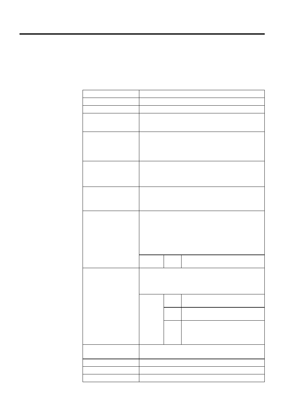
The table below shows the specifications of the Absolute Encoder Battery Module.
Specifications of Battery Module
Item
Specifications
Name
Absolute Encoder Battery Module
Model
JRMSP-120XCP96000
Maximum number of axes
to which power can be
supplied
8 axes
Indicators
POWER: Lit when external 24 VDC power is supplied to CN1 con-
nector. This indicator is not lit while a battery voltage check refer-
ence is being issued.
ALARM1: Lit when the battery voltage drops below 3.3 V.
ALARM2: Lit when the battery voltage drops below 3.0 V.
Battery Specifications
Model: ER6VC3 Battery (Toshiba) with connector (Yaskawa speci
fications)
Voltage: 3.6 V
Current capacity: 2,000 mAh
Maximum number of days
in which battery must be
replaced after low battery
voltage is detected
14 days after the ALARM1 indicator lights up (battery voltage drops
below 3.3 V), provided that all eight axes are connected, no power is
supplied to the Motion Module or Servo Amplifier, and the motor
does not rotate due to external force, etc.
External Input Signal
Signal type: 24 VDC, sourcing input (sinking input)
Input current: 5 mA
OFF current (1 mA or less)
Input conditions: ON voltage (supply voltage: -9 V) or more
(sinking: 9 V or more), OFF voltage (supply
voltage: -5 V) or less
Input impedance: 4.7 k
Ω
Signal
name
CHK
Battery voltage check reference. This signal
checks battery voltage when turned ON.
External Output Signal
Signal type: 24 VDC, sinking output (open collector)
Load current: 50 mA, OFF current (1 mA or less)
Load voltage: 20.4 to 28.8 VDC, 35 VDC (at peak), ON voltage
(1.5 V, 50 mA)
Signal
names
ALM1
Alarm 1. This signal is turned OFF when
battery voltage drops below 3.3 V.
ALM2
Alarm 2. This signal is turned OFF when
battery voltage drops below 3.0 V.
PON
Power ON. This signal is ON while 24 VDC
external power is being supplied to CN1
connector. This signal is OFF while battery
voltage check reference is being issued.
Delay Time
Power ON
→ ALM1/ALM2 output: 100 ms or less
CHK signal input
→ ALM1/ALM2 output: 10 ms or less
Protective Circuit
Battery charging prevention diode
Supply Voltage
20.4 to 28.8 VDC (external power supply)
Current Consumption
0.2 A or less