Ladder logic program example – Yaskawa MP920 User's Manual Design User Manual
Page 135
4.2 Control Modes
4-21
4
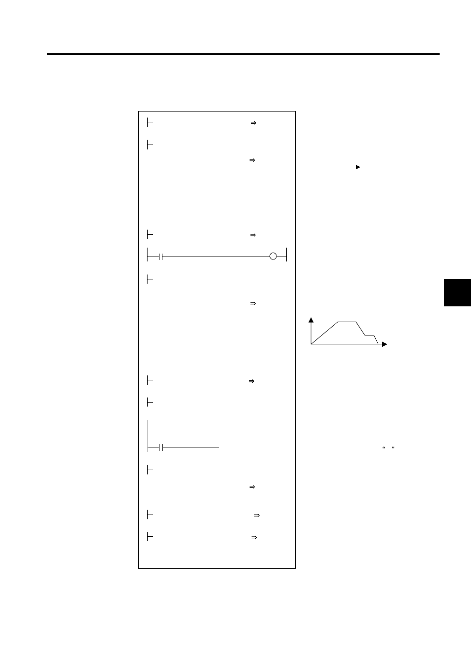
Ladder Logic Program Example
Fig. 4.10 RUN Command (DWG H04)
The example in the above illustration has been greatly simplified. In actual operation, each
register can be controlled from the user program.
Denominator *MW00041
High-speed scan setting: SW0004
Calculate the speed scaling constant (ks).
H0188
RUNMOD
OWC000
Set the phase control mode to ON.
Set Phase Reference Generation Operation
Disable to ON.
MW00040
×SW00004
K1
TsH
÷MW00041
K2
KS
ML03010
NR
× FBppr × n
60
× 10
4
10000
FFGAIN
MW03012
RUN
OBC0010
PREPARE
MB010010
ML03030
MA03050
FGN
ML03020
ML03020
ML03022
-ML03024
00000
DEND
Numerator *MW00040
NR = Rated speed
FBppr = Number of feedback pulses
n = Number of pulse multipliers (1, 2, or 4)
Note
Feed forward gain [10000/100%]
Driver RUN command (RUN)
When MB01010 turns ON, phase control
starts.
The phase reference displacement [pulse] is
read from the FGN function.
The FGN pattern is set in advance.
Position reference
Displacement x
Changes [pulses] per scan
When RUN command MB010020 turns ON,
the machine operates at the reference speed
NREF. When MB010020 turns OFF, the refer-
ence speed NREF remains at 0.
Standard speed reference setting [0.01%]
Phase compensation setting [pulse]
Phase reference previous displacement value
[pulse]
PHASE REFERENCE
DISPLACEMENT PATTERN
DISPLACEMENT X
DISPLACEMENT X
PREVIOUS VALUE
CHANGE
RUN command
CHANGE
Position bias
DISPLACEMENT X
PREVIOUS VALUE
DISPLACEMENT X
MB010020
[ ML03022]
×MW03012
FFGAIN
÷ML03010
KS
NREF
OWC015
[ ML03022]
[+MW03020]
PHBIAS
[ OLC016]
ML03020
ML03024
Reduce the fraction to the lowest terms so
that it can be stored as one word.