Yaskawa MP920 User's Manual Design User Manual
Page 94
3 Basic System Operation
3.4.3 Motion Programming
3-20
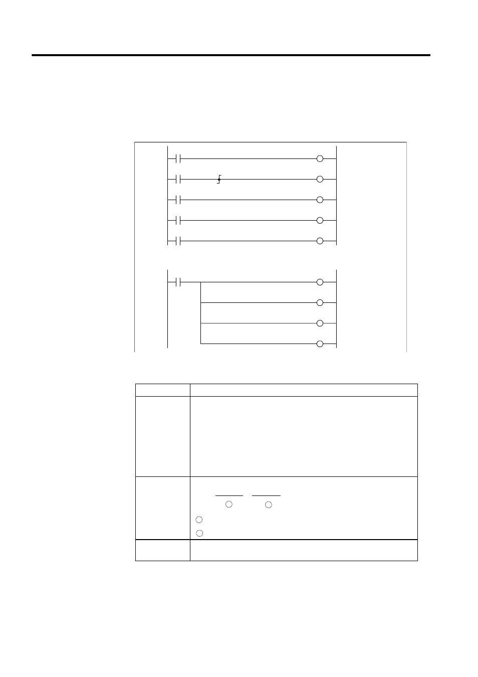
Example of a Ladder Logic Program for Motion Program Control
1. The minimum ladder logic program required to control a motion program is shown in the
following illustration.
2. The contents of this ladder logic program are shown in the following table.
3. When the external input signals (IB00000 to IB00007) connected to the MP920 are input
to DW00001 (second word of MSEE work registers) as motion program control signals
using the ladder logic program shown above, motion program operations such as run,
stop and pause can be performed by the system motion management functions.
Step Number
Program Content
1 to 7
The signals connected to the MP920 external input signals are stored as the
motion program control signals.
IW0000 (external input signals)
→ DW00001 (second word of MSEE work
registers)
• Program operation start
• Program pause
• Program stop
• Alarm reset
8
Calls motion program MPM001
MSEE MPM001 DA00000
Motion program number
MSEE work register address
11 to 15
Resets the alarm (bit 6 of OW00) using the alarm reset signal
(IB00005), and clears the alarm for each axis.
Servo ON
Program start
Program pause
Program stop
Alarm reset
Axis 1 alarm reset
Axis 2 alarm reset
Axis 3 alarm reset
Axis 4 alarm reset
1 0000
IB00000
DB000020
DB000010
IB00100
OBC0010
IB00001
DB000011
1 0002
1 0005
IB00002
DB000012
1 0007
IB00005
DB000015
1 0009
1 0011
MSEE
MPM001
DA00000
IB00005
OBC0006
1 0013
OBC0406
OBC0806
OBC0C06
1 0015
1 0017
1 0019
1
2
1
2